
Brake shoe with multi-function metal insert

a multi-functional, metal insert technology, applied in the direction of braking elements, braking members, friction linings, etc., can solve the problems of contaminating the city streets where the trolley cars are located, affecting the service life of the trolley, and requiring periodic cleaning of cast iron residue from the city streets, so as to reduce the amount of cast iron metal residue contaminating and reduce the cost of tooling.

Active Publication Date: 2011-06-09
RFPC HLDG CORP
View PDF19 Cites 10 Cited by
  • Summary
  • Abstract
  • Description
  • Claims
  • Application Information

AI Technical Summary

Benefits of technology

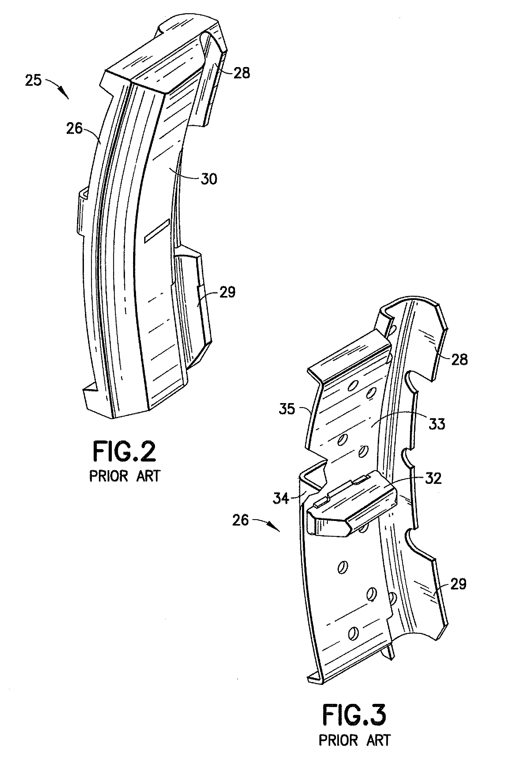
[0012]The composition brake shoe design of the present invention reduces the amount of cast iron metal residue contaminating the city streets to a level that should not require special cleaning. The inventive brake shoe also utilizes a symmetrical shape and a uniform thickness of friction material resulting in a single brake shoe design which can be installed at all locations of the vehicle. Further still, the brake shoe design of the invention has a flange guide located at a central portion of the shoe, as opposed to the ends of the shoe, which reduces the tooling cost required to produce the brake shoe, allowing for a replacement composition brake shoe to be produced at a competitive price.

Problems solved by technology

Additionally, since these brake shoes are produced from cast iron material, as the brakes are applied, cast iron wear particles and dust contaminate the city streets where the trolley cars operate.
Presently, considerable expense is incurred to periodically clean the cast iron residue from the city streets.

Method used


Image

  • Brake shoe with multi-function metal insert
  • Brake shoe with multi-function metal insert
  • Brake shoe with multi-function metal insert

Examples


Embodiment Construction

[0022]For purposes of the description hereinafter, spatial or directional terms shall relate to the invention as it is oriented in the drawing figures. However, it is to be understood that the invention may assume various alternative variations, except where expressly specified to the contrary. It is also to be understood that the specific components illustrated in the attached drawings, and described in the following specification, are simply exemplary embodiments of the invention. Hence, specific dimensions and other physical characteristics related to the embodiments disclosed herein are not to be considered as limiting.

[0023]The present invention can be characterized as a relocation of the flange guide portion of the brake shoe design which allows for the simplification of tooling and a combination of design features when producing the backing plate assembly. By relocating the flange guiding portion of the brake shoe to the center of the brake shoe instead of at the ends of the ...


PUM


Abstract

The invention is directed to an insert for a backing plate assembly for a composition friction brake shoe. The insert is particularly useful in the formation of a universal brake shoe for use with a trolley car braking system. The insert includes a central member having a first and second set of attachment posts extending from the respective ends thereof. These first and second sets of attachment posts are adapted for securing a first and second backing plate strap, respectively, thereto. A key bridge extends through a back portion of the central member and is configured for attachment to a brake shoe. A flange guide support extends from a side portion of the insert and includes legs defining a channel that runs parallel to the insert. The flange guide support is adapted for contacting a wheel flange to align a brake shoe with the wheel during braking of the vehicle.

Description

CROSS-REFERENCE TO RELATED APPLICATIONS[0001]This application is based on and claims priority to Provisional Patent Application No. 61 / 088,135, entitled “Brake Shoe With Multi-Function Metal Insert”, filed Aug. 12, 2008, which is hereby incorporated by reference in its entirety.BACKGROUND OF THE INVENTION[0002]1. Field of the Invention[0003]The present invention relates, in general, to a backing plate for a brake shoe for use in a trolley car braking system and, more particularly, to a multi-functional metal insert for use with a backing plate assembly in the formation of composite brake shoes for use in trolley car braking systems.[0004]2. Description of Related Art[0005]Milan type trolley cars, which are mass-transportation systems common in several cities, such as San Francisco, Calif., currently use cast-iron brake shoes in their braking systems. Examples of these types of brake shoes, generally indicated as 10, are shown in FIGS. 1A and 1B. These brake shoes include a U-shaped ...

Claims


Application Information

Patent Timeline
Patent Type & Authority Applications(United States)
IPC IPC(8): F16D65/02F16D69/00
CPCF16D65/0037F16D2069/002F16D65/062
Inventor RUMPH, TIMOTHY A.SHUTE, BRUCE W.PETZOLDT, MARTIN
Owner RFPC HLDG CORP
Learn More