
Image forming device and method therefor

a technology of forming device and image, which is applied in the direction of electrographic process apparatus, power supply for data processing, instruments, etc., can solve the problems of unnecessary power consumption, and achieve the effect of reducing waiting time and suppressing unnecessary power consumption

Inactive Publication Date: 2011-06-02
OKI DATA CORP
View PDF8 Cites 15 Cited by
  • Summary
  • Abstract
  • Description
  • Claims
  • Application Information

AI Technical Summary

Benefits of technology

"The present invention is an image forming device that can save power by shifting to a power saving mode when there is no printing activity for a set amount of time. The device measures the time it takes to stand still and calculates a count value based on the number of times the standby mode has reached a certain reference time. This count value is used to determine the optimal time to shift to the power saving mode. By dynamically adjusting the power saving mode shifting time based on changes in the frequency of printing job data, the device can effectively reduce unnecessary power consumption and improve printing efficiency."

Problems solved by technology

(a) Because the power saving mode is not started unless the preset power saving mode shifting time has elapsed, unnecessary power is consumed while print job data is sparsely received from the higher-level device.

Method used


Image

  • Image forming device and method therefor
  • Image forming device and method therefor
  • Image forming device and method therefor

Examples


first embodiment

Advantages of First Embodiment

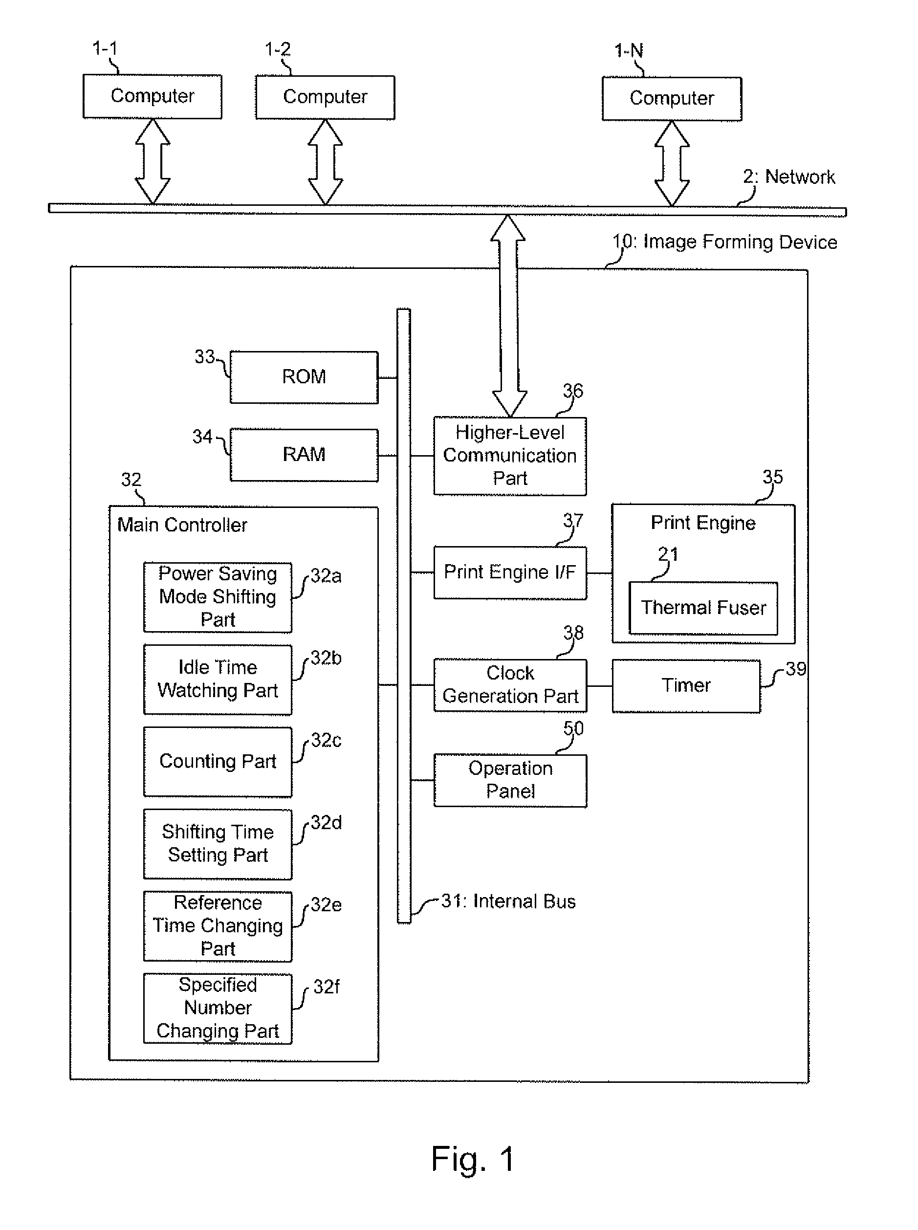
The following advantages may be obtained by the image forming device 10 according to the present first embodiment.

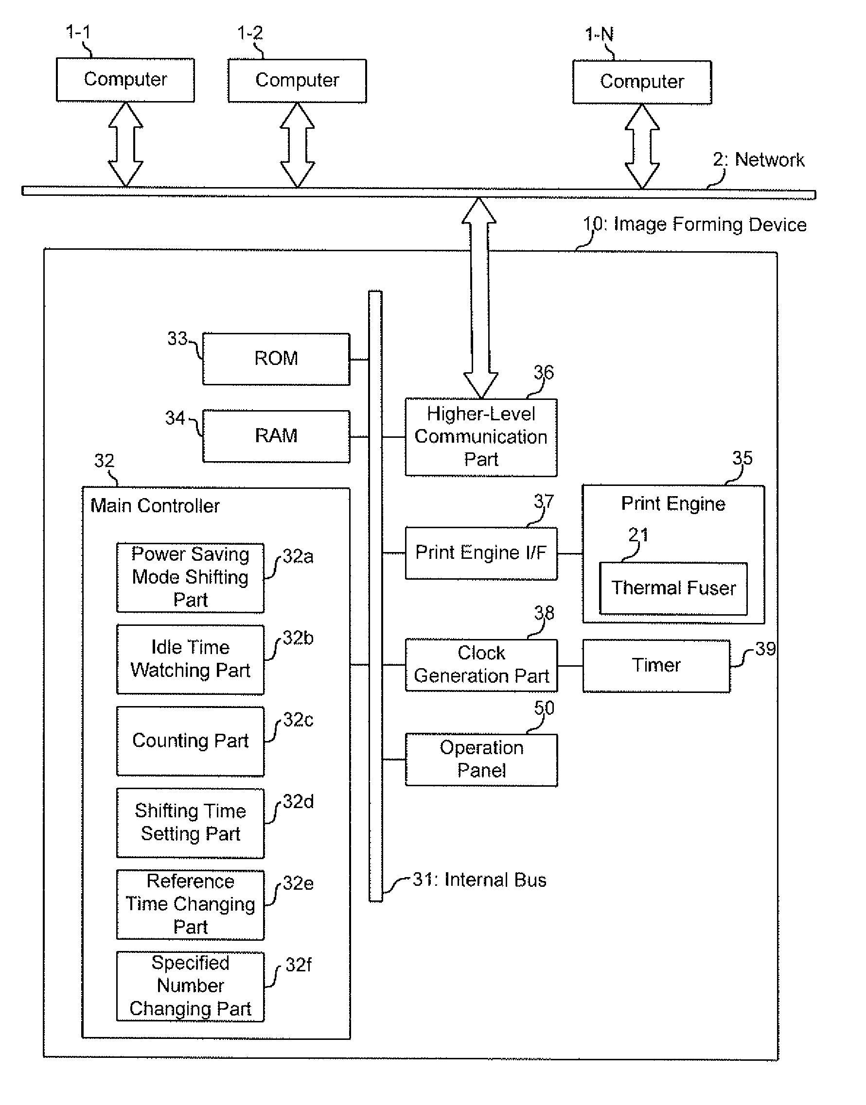
As a result of watching the time of the standby mode, during which the data watching timer 39 waits for print data, if the time of the standby mode is continuous and equal to or longer than the certain reference time (e.g., 15 minutes), the consecutive repeat count N is incremented by one. If the consecutive repeat count N becomes equal to or greater than the specified number, the shorter power saving mode shifting time Ts2 (e.g., 1 minute) is set. If the time of the standby mode is less than the certain reference time (e.g., 15 minutes), the longer power saving mode shifting time Ts1 (e.g., 30 minutes) is set. Therefore, an appropriate power saving mode shifting time can be set by dynamically responding to the changes in frequency of the print data, regardless of the day of the week and / or time periods.

As a result, power consumption is redu...

second embodiment

Advantages of Second Embodiment

According to the image forming device 10A of the second embodiment, in addition to the advantages of the first embodiment, the power saving mode shifting time is set based on the consecutive repeat count N by providing the power saving mode shifting time decision table 60. Therefore, a finer setting of the power saving mode shifting time can be achieved. As a result, power consumption is reduced when the frequency of the image data is low, and when the frequency of the print data increases, the waiting time is reduced for starting printing.

(Modifications)

The present invention is not limited to the above-described embodiments, and various usages and modifications may be possible. Below (a)-(d) are some the examples of such usages and modifications.

(a) In the first and second embodiments, a color page printer was discussed as the image forming devices 10 and 10A. However, the present invention is not limited to color page printers. The present invention ...


PUM


Abstract

An image forming device that forms an image on a print medium includes a power saving mode shifting part that shifts a mode of the image forming device to a power saving mode, in which power consumption is decreased, when a set power saving mode shifting time has elapsed during a standby mode, an idle time watching part that measures an idle time in the standby mode from a time of a completion of a previous printing to a time of starting a subsequent printing, a counting part that counts a number of times that the idle time has been equal to or longer than a preset idle reference time, wherein the number of times is a count value, and a shifting time setting part that sets the power saving mode shifting time in response to the count value.

Description

CROSS REFERENCE TO RELATED APPLICATIONThe present application is related to, claims priority from and incorporates by reference Japanese Patent Application Number 2009-270007, filed on Nov. 27, 2009.TECHNICAL FIELDThe present invention relates to an image forming device that has a power saving mode, under which power consumption is reduced while the image forming device stands by. The present invention also relates to a method for the image forming device.BACKGROUNDImage forming devices, such as a color page printer, a photocopy machine and a multifunction machine, conventionally includes a power saving function. These image forming devices control power consumption by terminating power supply to a thermal fuser that consumes a large amount of electricity and by shifting to a power saving mode when print data is not received from a higher-level device, such as a computer, after elapsing a power saving mode shifting time, which is preset in advance, after completion of a print operat...

Claims


Application Information

Patent Timeline
Patent Type & Authority Applications(United States)
IPC IPC(8): G06F1/32
CPCG03G15/5004
Inventor OGASHIWA, AKIYOSHI
Owner OKI DATA CORP
Learn More