
Imaging apparatus

a technology of image signal and frame frequency, applied in the field of image signal comb noise, can solve the problems of not visually recognizable signal blinking on and off in an extremely short time cycle, out of frame frequency of image signal, especially serious problem for drive recorder, etc., and achieve the effect of preventing the occurrence of comb nois

Active Publication Date: 2011-06-02
RICOH KK
View PDF5 Cites 16 Cited by
  • Summary
  • Abstract
  • Description
  • Claims
  • Application Information

AI Technical Summary

Benefits of technology

[0010]Accordingly, an object of the present invention is to provide an imaging apparatus less susceptible to a blink cycle of lighting devices such as LED traffic signals, capable of using display devices using the NTSC system, and preventing occurrence of comb noise.
[0011]Another object of the present invention is to provide a low-cost imaging apparatus capable of reading out image data from an imaging element at a frame frequency out of a frame frequency of the NTSC system using a simple configuration.

Problems solved by technology

However, when a car-mounted camera takes an image of a display device such as an on-street LED traffic signal, the following problem occurs.
Therefore, the signal blinks on and off in an extremely short time cycle that is not visually recognizable.
This is a particularly serious problem for a drive recorder.
However, the frame frequency of an image signal is out of the frame frequency of the NTSC system, and cannot be displayed in a display device of the NTSC system.
However, the following fresh problem then occurs.
Therefore, a time for writing one frame of image data in the frame memory and a time for reading out one frame of image data from the frame memory differ from each other, and a comb noise specific to the interlace method is made even when the frame memory is a double buffer.

Method used


Image

  • Imaging apparatus
  • Imaging apparatus
  • Imaging apparatus

Examples


embodiment 1

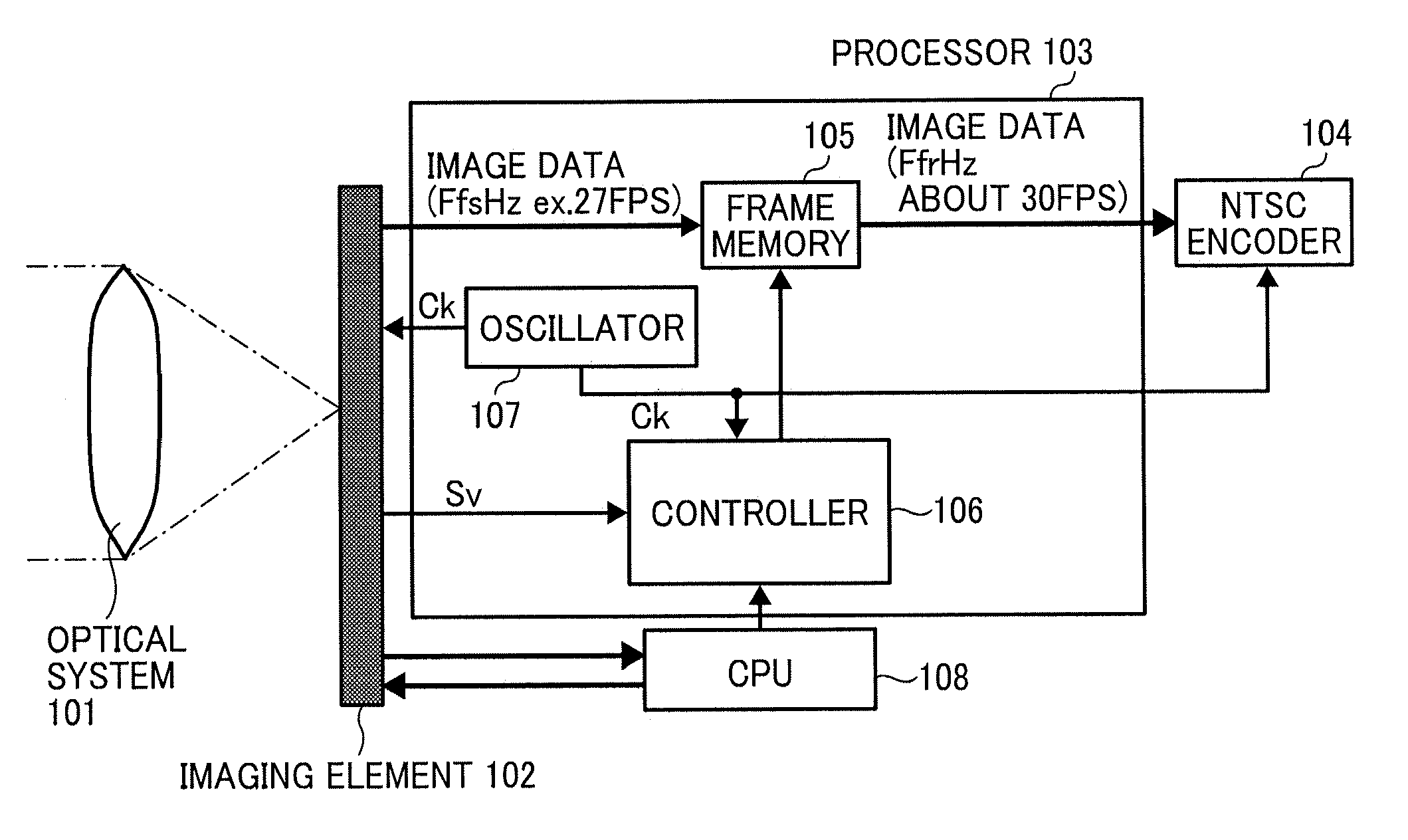
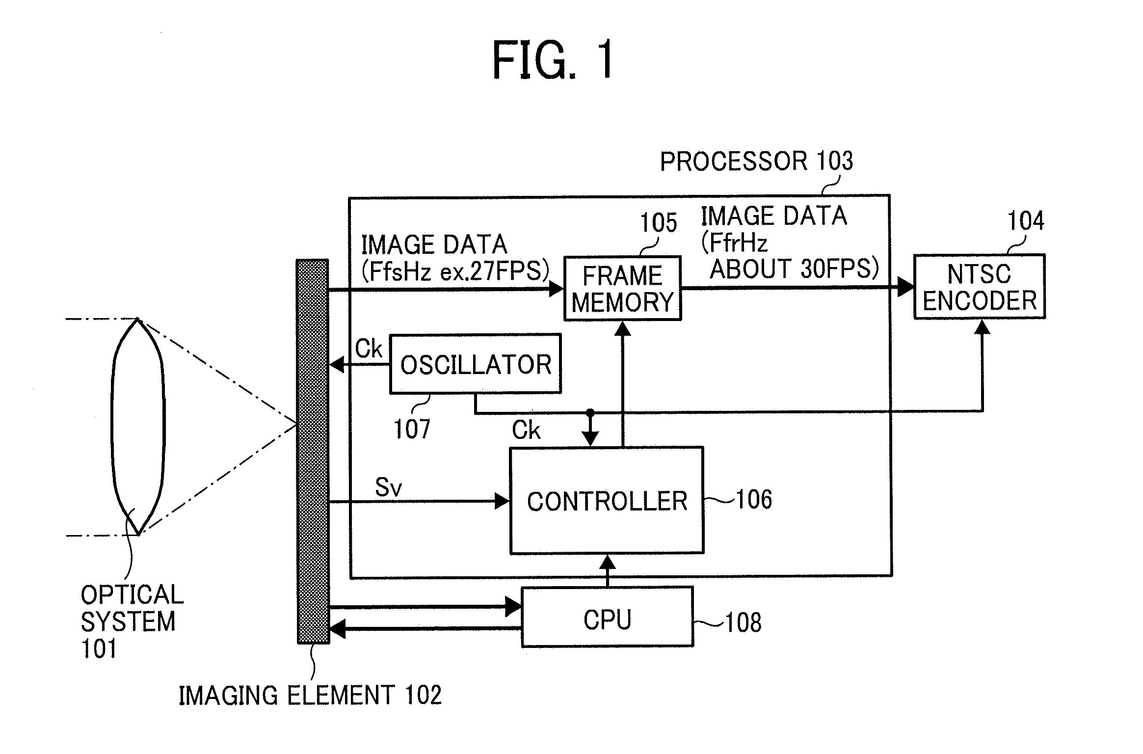
[0053]Hereinafter, embodiments of the present invention will be explained, referring to the drawings. FIG. 1 is a whole configuration diagram of an embodiment (Embodiment 1) of the imaging apparatus of the present invention. The imaging apparatus includes an optical system 101, an imaging element 102, a processor 103, an NTSC encoder 104, a CPU 108 controlling the all operations, etc. The processor 103 includes a frame memory 105, a controller 106 and an oscillator 107. The NTSC encoder 104 is connected with a display device and an image recorder of the NTSC system, but they are omitted in FIG. 1. The oscillator 107 is a crystal element generating a clock signal having a frequency of 13.5 MHz for the NTSC system. The oscillator 107 gives a clock (CK) to the controller 106, the NTSC encoder 104, and further to the imaging element 102 as well in the processor 103.

[0054]The imaging element 102 receives a clock having a frequency of 13.5 MHz for the NTSC system from the oscillator 107, ...

embodiment 2

[0122]FIG. 23 is a whole configuration diagram of another embodiment (Embodiment 2) of the imaging apparatus of the present invention. The imaging apparatus includes an optical system 101, an imaging element 102, a processor 103, an NTSC encoder 104, a CPU 108 controlling the all operations, etc. The processor 103 includes a frame memory 105, a controller 106, an oscillator 107 and a PLL 109. The NTSC encoder 104 is connected with a display device and an image recorder of the NTSC system, but they are omitted in FIG. 23. The oscillator 107 is a crystal element generating a clock signal for the NTSC system. The PLL 109 produces a clock frequency CK (13.5 MHz) for the NTSC system as it is when receiving it from the oscillator 107, and at the same time, and forms a clock frequency CK′ out of the clock frequency CK (13.5 MHz) for the NTSC system. A chip including the controller includes the PLL 109 as well, and new components are not needed and the configuration if FIG. 23 can be realiz...


PUM


Abstract

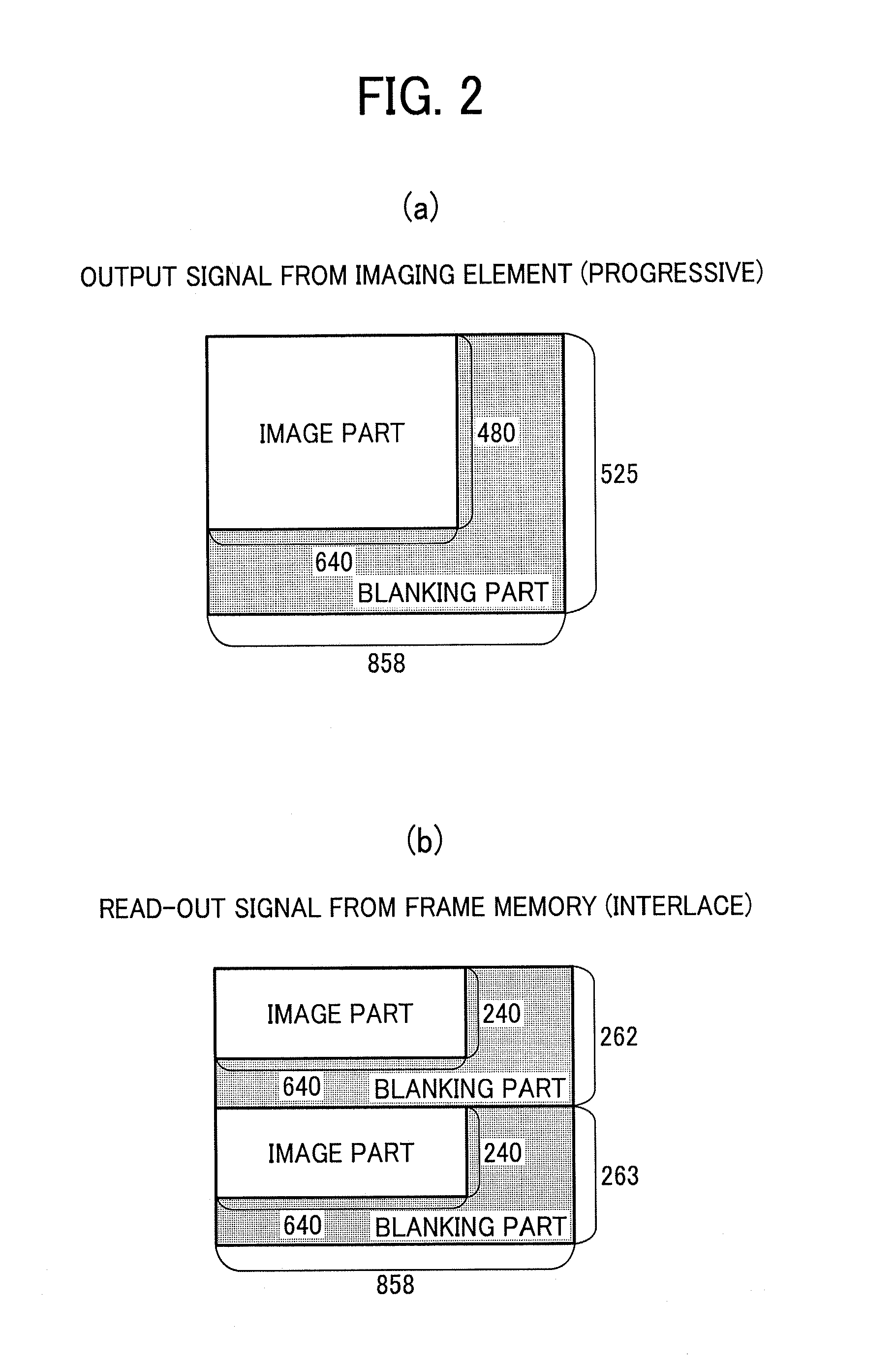
An imaging apparatus, including an optical system forming an image of an optical image of an object; an imaging element imaging the optical image and producing image data at a frame frequency Ffs out of a frame frequency Ffr of NTSC system; a frame memory storing the image data; and a controller progressively writing the image data in the frame memory and interlacedly reading out the image data from the frame memory at the frame frequency Ffr of NTSC system. The frame memory is divided into at least three areas comprising a writing-in area and a read-out area, wherein the controller sequentially switches the areas of the frame memory and progressively writes one frame of image data in each area and interlacedly reads out one frame of image data from each area in sequence.

Description

BACKGROUND OF THE INVENTION[0001]1. Field of the Invention[0002]The present invention relates to an imaging apparatus such as a car-mounted camera, and more particularly to an imaging apparatus using the NTSC system.[0003]2. Description of the Background Art[0004]To accommodate display devices using the NTSC system, car-mounted cameras typically take images at 30 fps with an imaging element such as a CMOS sensor. However, when a car-mounted camera takes an image of a display device such as an on-street LED traffic signal, the following problem occurs.[0005]The LED traffic signal is driven by a drive voltage coming from a full-wave rectified commercial AC source. Therefore, the signal blinks on and off in an extremely short time cycle that is not visually recognizable. Thus, in a frame, when a charge accumulation time of the imaging element and a light-out period of the signal overlap, the signal appears to be out in the frame even though a red, blue or green light is actually on. Wh...

Claims


Application Information

Patent Timeline
IPC IPC(8): H04N5/76
CPCH04N5/378H04N7/0127H04N7/012H04N7/0105H04N25/75
Inventor ISHIGAKI, TOMOKOKASAHARA, RYOSUKE
Owner RICOH KK
Learn More