
Imaging device and imaging device control method

Active Publication Date: 2011-05-26
OM DIGITAL SOLUTIONS CORP
View PDF8 Cites 47 Cited by
  • Summary
  • Abstract
  • Description
  • Claims
  • Application Information

AI Technical Summary

Benefits of technology

[0007]The present invention has as its object to provide an imaging device with which it is possible to take pictures with a natural feeling without any sense of unease at the time of shooting, and an imaging device control method.

Problems solved by technology

However, with digital cameras, which have become widespread in recent years, the depth of field becomes deep due to the surface area of the imaging section being small, and even when shooting with the same angle of view as with a film camera prominent background bokeh is not achieved.

Method used


Image

  • Imaging device and imaging device control method
  • Imaging device and imaging device control method
  • Imaging device and imaging device control method

Examples


Embodiment Construction

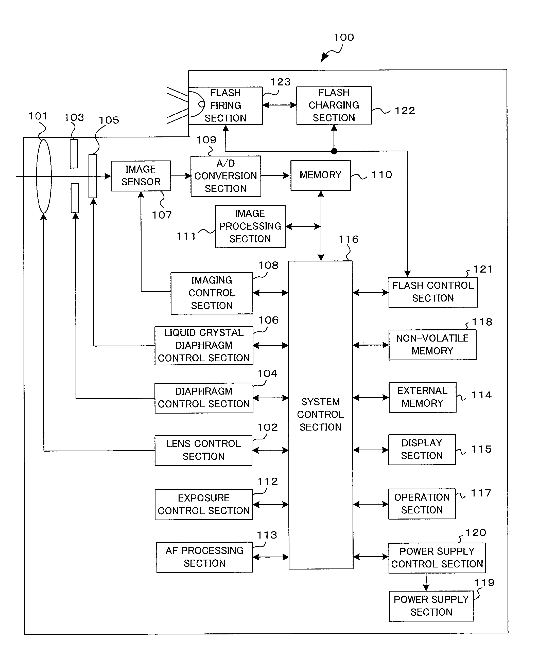
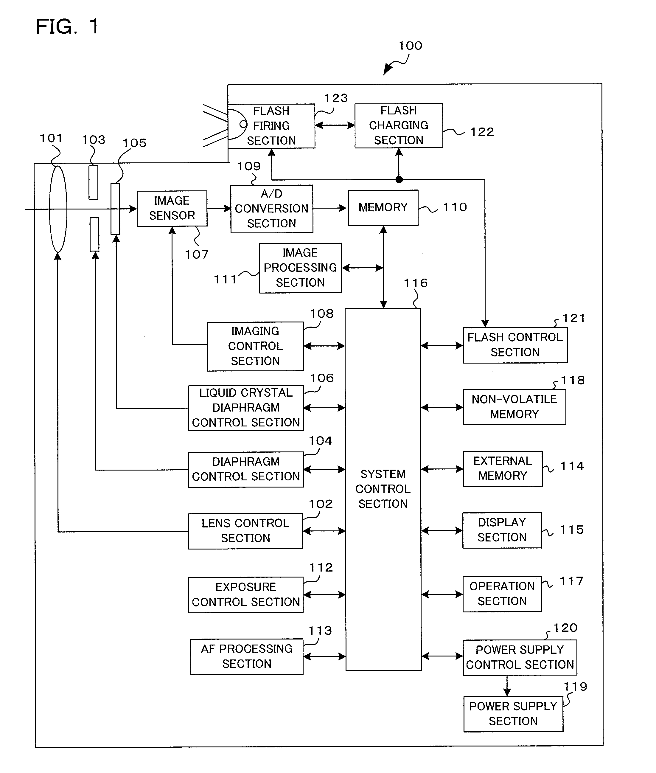
[0038]Preferred embodiments using a camera to which the present invention has been applied will be described in the following in accordance with the drawings. A camera 100 of a first embodiment of the present invention is a digital camera, and to describe it briefly has an imaging section, with a subject image being converted to image data by this imaging section, and the subject image then being subjected to live view display on a display section based on this converted image data. A photographer determines composition and photo opportunity by looking at the live view display at the time of shooting. If a release operation takes place shooting is carried out. At this time, charge accumulation of photoelectric current for pixels of a first frame image with a wide-open aperture value is carried out, the diaphragm is then stopped down once charge accumulation for the first frame is completed, and image data based on charge accumulation of the first frame is read out during this stoppi...


PUM


Abstract

An imaging device of the present invention comprises an imaging section for photoelectrically converting a subject image, and outputting image data, an aperture control section for narrowing subject light flux at a first aperture value and a second aperture value, a shooting control section for, in response to a release instruction, imaging a first image at the first aperture value and, reading out first image data from the imaging section while simultaneously carrying out a stopping down operation to the second aperture value, imaging a second image at the second aperture value and, reading out second image data from the imaging section, and an image processing section for detecting an amount of variation in contrast value for each location in the first image data and the second image data, and carrying out processing to blur at an intensity of blurring according to the amount of variation between each location.

Description

[0001]Benefit is claimed, under 35 U.S.C. §119, to the filing date of prior Japanese Patent Application No. 2009-267289 filed on Nov. 25, 2009. This application is expressly incorporated herein by reference. The scope of the present invention is not limited to any requirements of the specific embodiments described in the application.BACKGROUND OF THE INVENTION[0002]1. Field of the Invention[0003]The present invention relates to an imaging device, and to a control method for an imaging device.[0004]2. Description of the Related Art[0005]Depth of field of a taken image varies depending on optical characteristics such as aperture value and focal length. When shooting in sports mode using a telephoto lens, a deep depth of field is preferred. When taking a portrait photograph, however, bokeh, or blurring, is used in a way that is pleasing to the eye. With a 135 film camera (35 mm silver halide film camera), it is possible to sufficiently vary the depth of field by appropriately selecting...

Claims


Application Information

Patent Timeline
IPC IPC(8): H04N5/235
CPCH04N1/00114H04N1/2112H04N5/23293H04N5/2356H04N9/74H04N5/243H04N5/353H04N5/3532H04N5/238H04N23/673H04N23/743H04N23/63H04N23/75H04N23/76H04N25/531H04N25/53
Inventor KUNISHIGE, KEIJISHIMADA, YOSHINAOHONDA, TSUTOMU
Owner OM DIGITAL SOLUTIONS CORP
Learn More