
Earmuff assembly

Active Publication Date: 2011-05-26
SOUND TEAM ENTERPRISE
View PDF79 Cites 10 Cited by
  • Summary
  • Abstract
  • Description
  • Claims
  • Application Information

AI Technical Summary

Benefits of technology

[0016]The present invention has been accomplished under the circumstances in view. It is the main object of the present invention to provide an earmuff assembly, which allows convenient adjustment of the length of the headband and the angular positions of the ear cups to fit different wearing conditions, and is covered with a soft fabric material for an optimal wearing comfort.
[0017]To achieve this and other objects of the present invention, an earmuff assembly comprises a length adjustable headband consisting of two headband elements, two ear cups, two connection devices that connect the coupling portions of the headband elements to the ear cups in such a manner that the angular positions of the ear cups are adjustable in X-axis direction as well as in Y-axis direction relative to the headband, and a soft fabric material covering the ear cups for an optimal wearing comfort. Thus, the user can adjust the length of the headband and the angle of the ear cups subject to the actual wearing requirements, assuring positive contact between the ears and the ear cups.
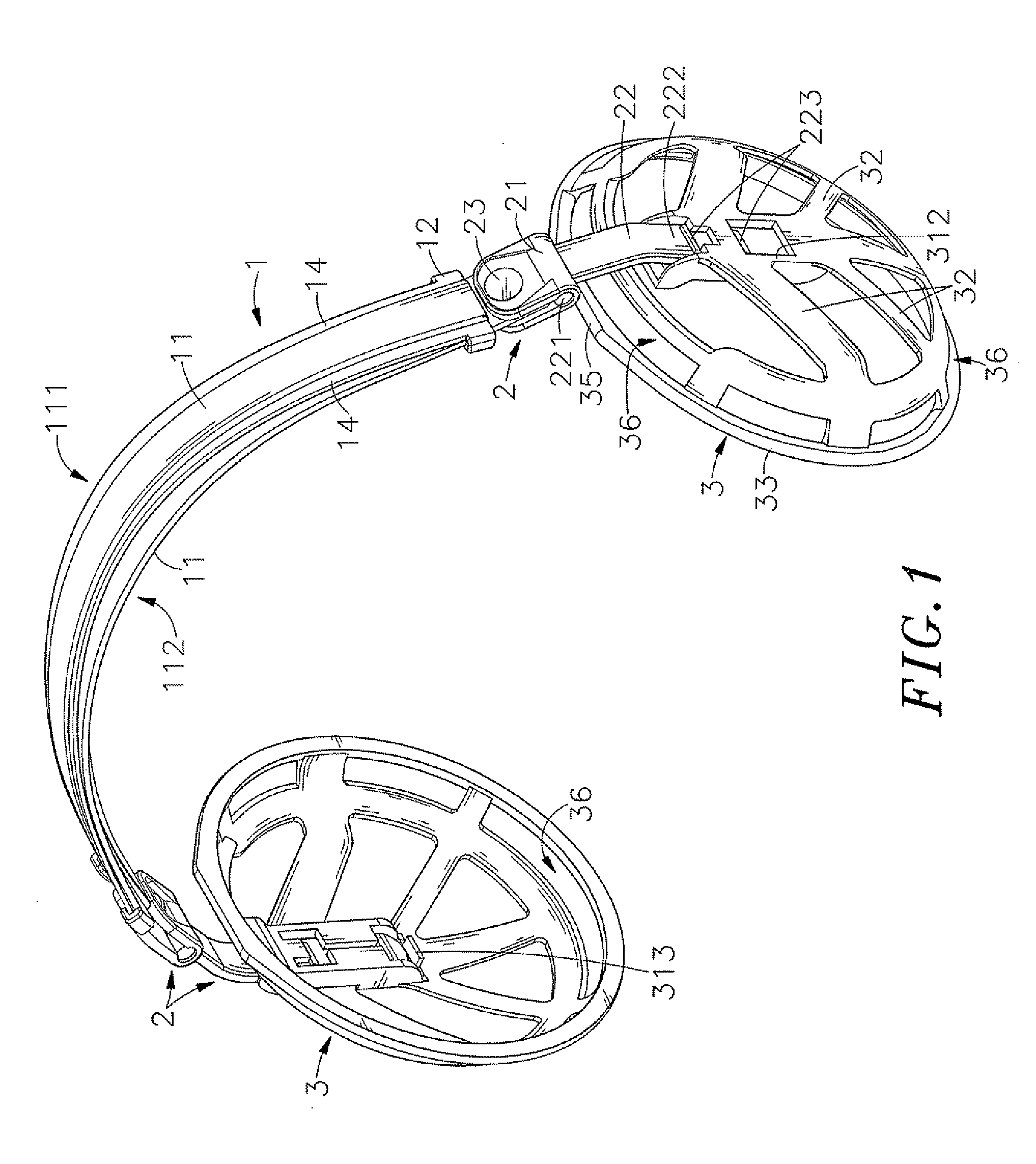
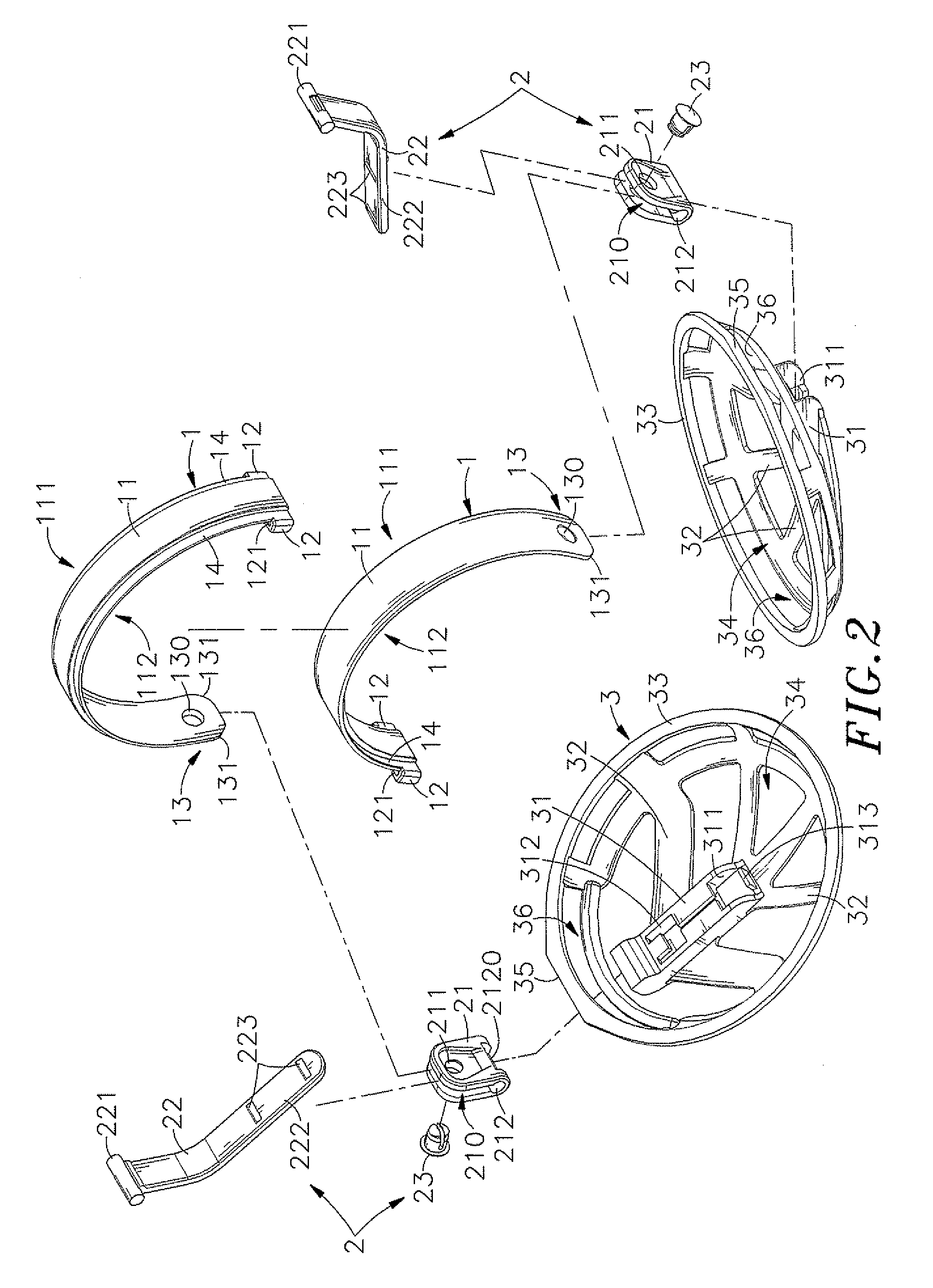
[0018]Further, each headband element comprises two constraint lugs bilaterally located on one end and a coupling portion located on the opposite end. The coupling portion of one headband element is inserted through a groove on each constraint lug of the other headband element so that the combined length of the headband elements of the headband is conveniently adjustable.
[0019]Further, each headband element comprises two sliding grooves bilaterally extending along the length between the two opposite ends thereof. Further, each headband element as a thickness gradually increasing in direction from the constraint lugs toward the coupling portion. When the two headband elements are arranged together, the constraint lugs of one headband element fit the sliding grooves of the other headband element, avoiding protrusion of the constraint lugs over the surface of the headband and keeping the outwardly curved outer surface and inwardly curved inner surface of each of the headband elements in a smoothly arched condition to fit the user's head positively and comfortably. When adjusting the length of the headband, no stress concentration will occur, avoiding headband deformation.
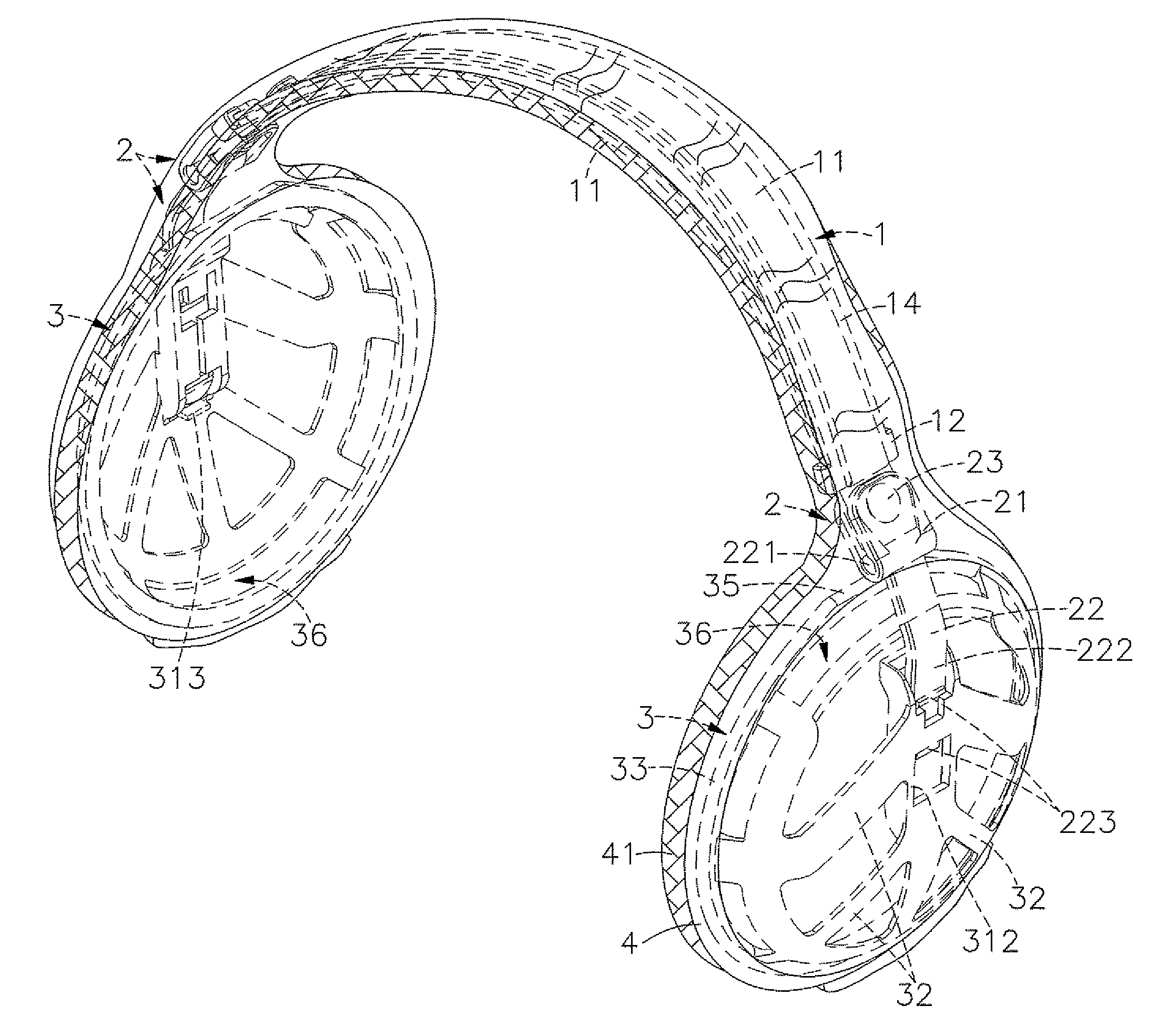
[0024]As the length of the headband is adjustable and the ear cups are biasable relative to the headband in X-axis direction as well as Y-axis direction, the earmuff assemblies can be received in a received condition with the two ear cups closely attached together to reduce the size, saving much the storage space and avoiding accidental damage.

Problems solved by technology

However, the aforesaid warm-keeping devices cannot directly protect the ears against the cold.
When exposing the ears to the cold weather, the ears may suffer from a freezing injury or become painful.
More particularly, when the cold wind passes or when one is in a low temperature place, cold mountain or snowland area, exposing the ears to the freezing air may cause a serious injury.
This design of ear protection device is still not satisfactory in function and has drawbacks as follows:1. The ear protection device can simply be attached to the user's head from the top side or the back.2. The looped portions A1 protrude over the bottom side of the headband A. When the user wears the ear protection device, the protruding looped portions A1 are directly stopped against the user's head, causing the head to feel uncomfortable.3. After adjustment of the length, the elements of the headband A may slip relative to the respective looped portions A1, and inconsequence, the ear cups B may fall from the ears accidentally.4. The ear cups B are respectively fastened to the ends of the headband A by a respective small fastening member D. When the user adjusts the angle of each ear cup B relative to the ears, the connection area between the headband A and the ear cup B may break easily, losing the functioning of the ear protection device.5. The ear cups B are not strong enough for positive positioning on the user's head around each ear to keep the ears well protected.6. The ear cups B are respectively affixed to the ends of the headband A. When not in use, the ear protection device cannot be collapsed to reduce the size for storage.

Method used


Image

  • Earmuff assembly
  • Earmuff assembly
  • Earmuff assembly

Examples


Embodiment Construction

[0041]Referring to FIGS. 1, 2 and 10, an earmuff assembly in accordance with a first embodiment of the present invention is shown comprising a headband 1, two ear cups 3 for covering the user's ears respectively, two connection devices 2 that connect the ear cups 3 to the two distal ends of the headband 1, and a soft fabric material 4.

[0042]The headband 1 consists of two reversed headband elements 11. Each headband element 11 comprises two constraint lugs 12 bilaterally located on one end thereof, an insertion groove 121 defined in each of the two constraint lugs 12, a coupling portion 13 located on the other end thereof, and two sliding grooves 14 bilaterally extending along the length between the two opposite ends thereof. The coupling portion 13 has two chamfered edges 131 bilaterally located on the distal end thereof, and a trough hole 130 spaced between the two chamfered edges 131.

[0043]Each connection device 2 consists of a substantially U-shaped connection plate 21, an elonga...


PUM


Abstract

An earmuff assembly includes a headband consisting of two headband elements each having two constraint lugs bilaterally located on one end and a coupling portion located on the opposite end, the coupling portion of one headband element being inserted through a groove on each constraint lug of the other headband element for allowing adjustment of the length of the headband, two ear cups, two connection devices that connect the coupling portions of the headband elements to the ear cups such that the angular positions of the ear cups are adjustable in X-axis direction as well as in Y-axis direction relative to the headband, and a soft fabric material covering the ear cups for an optimal wearing comfort.

Description

[0001]This application is a Continuation-In-Part of application Ser. No. 12 / 216,278, filed on Jul. 2, 2008, now pending. The patent application identified above is incorporated here by reference in its entirety to provide continuity of disclosure.BACKGROUND OF THE INVENTION[0002]1. Field of the Invention[0003]The present invention relates earmuffs and more particularly, to an earmuff assembly, which allows convenient adjustment of the length of the headband and the angular positions of the ear cups to fit different wearing conditions, and is covered with a soft fabric material for an optimal wearing comfort.[0004]2. Description of the Related Art[0005]In autumn and winter, people may dress in heavy clothes to protect the body against the cold. In addition to a fur coat, wind coat or snow coat, people may also wear hat, gloves, scarf, muff and / or other accessories for warmth. However, the aforesaid warm-keeping devices cannot directly protect the ears against the cold. When exposing ...

Claims


Application Information

Patent Timeline
IPC IPC(8): A42B1/00
CPCA61F11/06
Inventor CHIANG, TSUNG-PAI
Owner SOUND TEAM ENTERPRISE
Learn More