
Lighting apparatus; components thereof and assemblies incorporating the same

a technology of light-emitting apparatus and components, which is applied in the direction of lighting and heating apparatus, lighting support devices, and devices with built-in power, etc., can solve the problems of people who have inadequately-lighted areas by a variety of means

Active Publication Date: 2011-05-19
GOAL ZERO
View PDF14 Cites 25 Cited by
  • Summary
  • Abstract
  • Description
  • Claims
  • Application Information

AI Technical Summary

Problems solved by technology

Over time, people have illuminated inadequately-lighted areas by a variety of means including, for example: torches, oil lamps, candles and the like.

Method used


Image

  • Lighting apparatus; components thereof and assemblies incorporating the same
  • Lighting apparatus; components thereof and assemblies incorporating the same
  • Lighting apparatus; components thereof and assemblies incorporating the same

Examples


Embodiment Construction

[0020]The Figures illustrate an exemplary embodiment of a lighting apparatus, components thereof and assemblies incorporating the same in accordance with an embodiment of the invention. Based on the foregoing, it is to be generally understood that the nomenclature used herein is simply for convenience and the terms used to describe the invention should be given the broadest meaning by one of ordinary skill in the art.

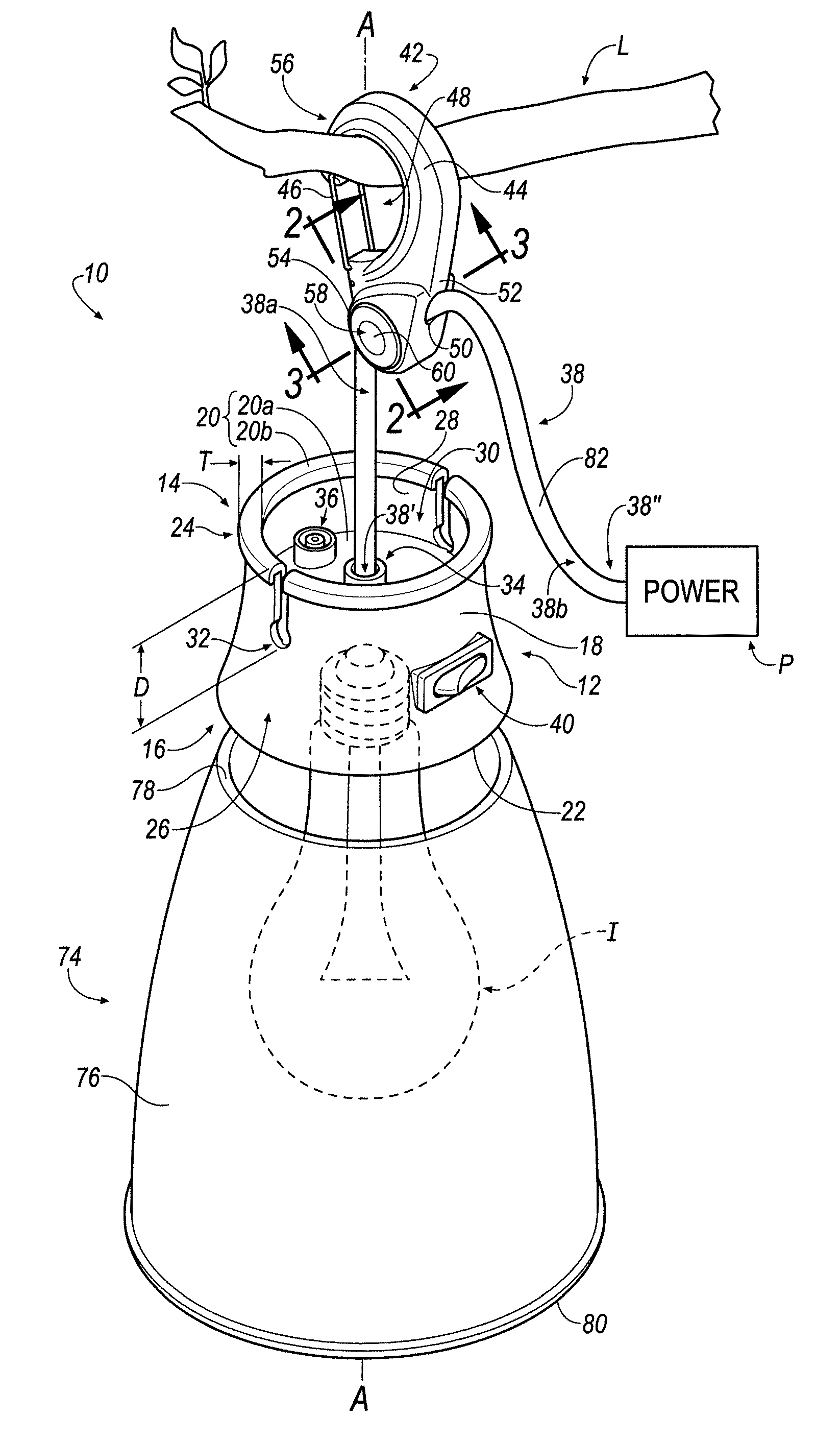
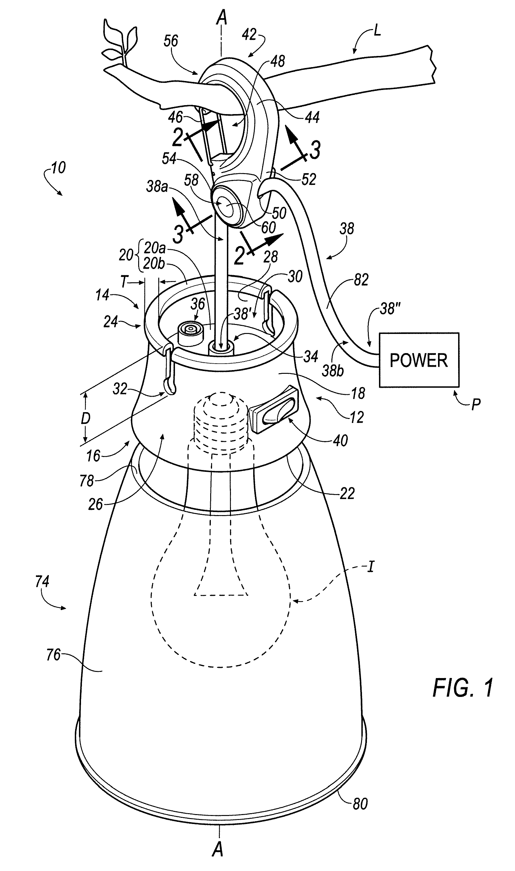
[0021]Referring to FIG. 1, a lighting apparatus is shown generally at 10 in accordance with an embodiment of the invention. In an embodiment, the lighting apparatus 10 includes a body portion 12 having an upper end 14 and a lower end 16. The body portion 12 includes an outer side surface 18, an upper surface 20 and a lower surface 22.

[0022]In an embodiment, the outer side surface 18 forms the body portion 12 to include a substantially cylindrical shape. In an embodiment, the outer side surface 18 tapers radially outwardly near the lower end 16. Although the body portion...


PUM


Abstract

A lighting apparatus includes a body portion, a conduit coupled to the body portion, and one or more illumination components coupled to the body portion, where the one or more illumination components are in electrical communication with the conduit. A lighting apparatus kit is also disclosed. A daisy-chained lighting apparatus assembly is also disclosed.

Description

CROSS REFERENCE TO RELATED APPLICATIONS[0001]This patent application claims the benefit of priority under 35 U.S.C. §119(e) of U.S. Provisional Application No. 61 / 261,656, having a filing date of Nov. 16, 2009, titled “Lighting Apparatus; Components Thereof and Assemblies Incorporating the Same,” the complete disclosure of which is hereby incorporated by reference.FIELD[0002]The disclosure relates to a lighting apparatus, components thereof and assemblies incorporating the same.DESCRIPTION OF THE RELATED ART[0003]There has always been a need to illuminate an otherwise inadequately-lighted area. Over time, people have illuminated inadequately-lighted areas by a variety of means including, for example: torches, oil lamps, candles and the like. Although such conventional means are acceptable for the purpose of illuminating an otherwise inadequately-lighted area, improvements over conventional illumination methodologies are still sought in order to advance the art.BRIEF DESCRIPTION OF T...

Claims


Application Information

Patent Timeline
Patent Type & Authority Applications(United States)
IPC IPC(8): F21V33/00F21S4/00
CPCF21S2/00F21S4/001F21S9/02F21S9/03F21V21/008F21Y2101/02F21V21/16F21V21/32F21V21/34F21V23/06F21V21/088F21S4/10F21Y2115/10
Inventor WORKMAN, ROBERT EMMETTKRANTZ, NORM
Owner GOAL ZERO
Learn More