
Inlet guide vane drive system with spring preload on mechanical linkage

Active Publication Date: 2011-05-12
HAMILTON SUNDSTRAND CORP
View PDF19 Cites 5 Cited by
  • Summary
  • Abstract
  • Description
  • Claims
  • Application Information

AI Technical Summary

Problems solved by technology

One challenge with these systems is that variables in the flow of air to the guide vanes, and the compressor, can cause vibration on the variable vanes, ring and sector gears, and across the mechanical linkage.

Method used


Image

  • Inlet guide vane drive system with spring preload on mechanical linkage
  • Inlet guide vane drive system with spring preload on mechanical linkage
  • Inlet guide vane drive system with spring preload on mechanical linkage

Examples


Embodiment Construction

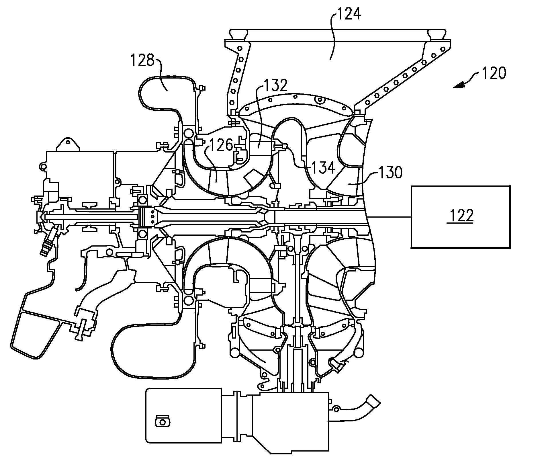
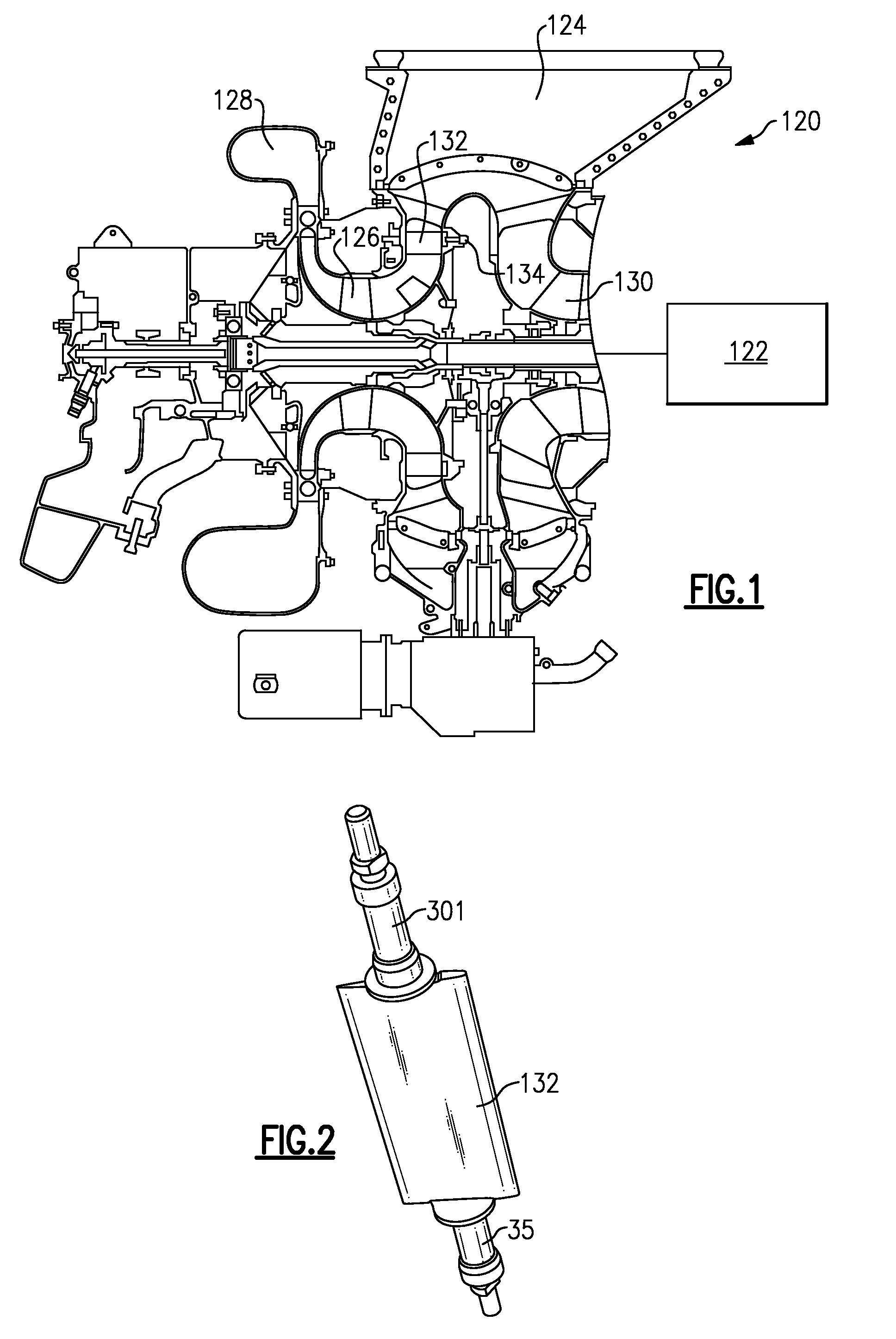
[0014]A turbine engine 120 is illustrated in FIG. 1. A power section 122 includes a combustion section and a turbine section, as known. A compressor section delivers compressed air to the combustion section. As shown, the compressor section includes an inlet plenum 124 delivering air from a source of air past a plurality of inlet guide vanes 132 toward a low pressure impeller 126. The low pressure impeller 126 delivers air to an outlet scroll 128. A high pressure compressor 130 delivers air to the combustion section. An actuator 134 actuates the inlet guide vanes 132 to pivot. The positioning of the inlet guide vanes, and the reason for changing their positions is known, and relates to delivering a supply of air to the low pressure compressor impeller 126 in desired quantities.

[0015]As shown schematically in FIG. 2, the inlet guide vanes 132 include pivot pins 35 and 301 which allow the orientation of the inlet guide vanes 132 to pivot, to change the angle of incidence of air approa...


PUM


Abstract

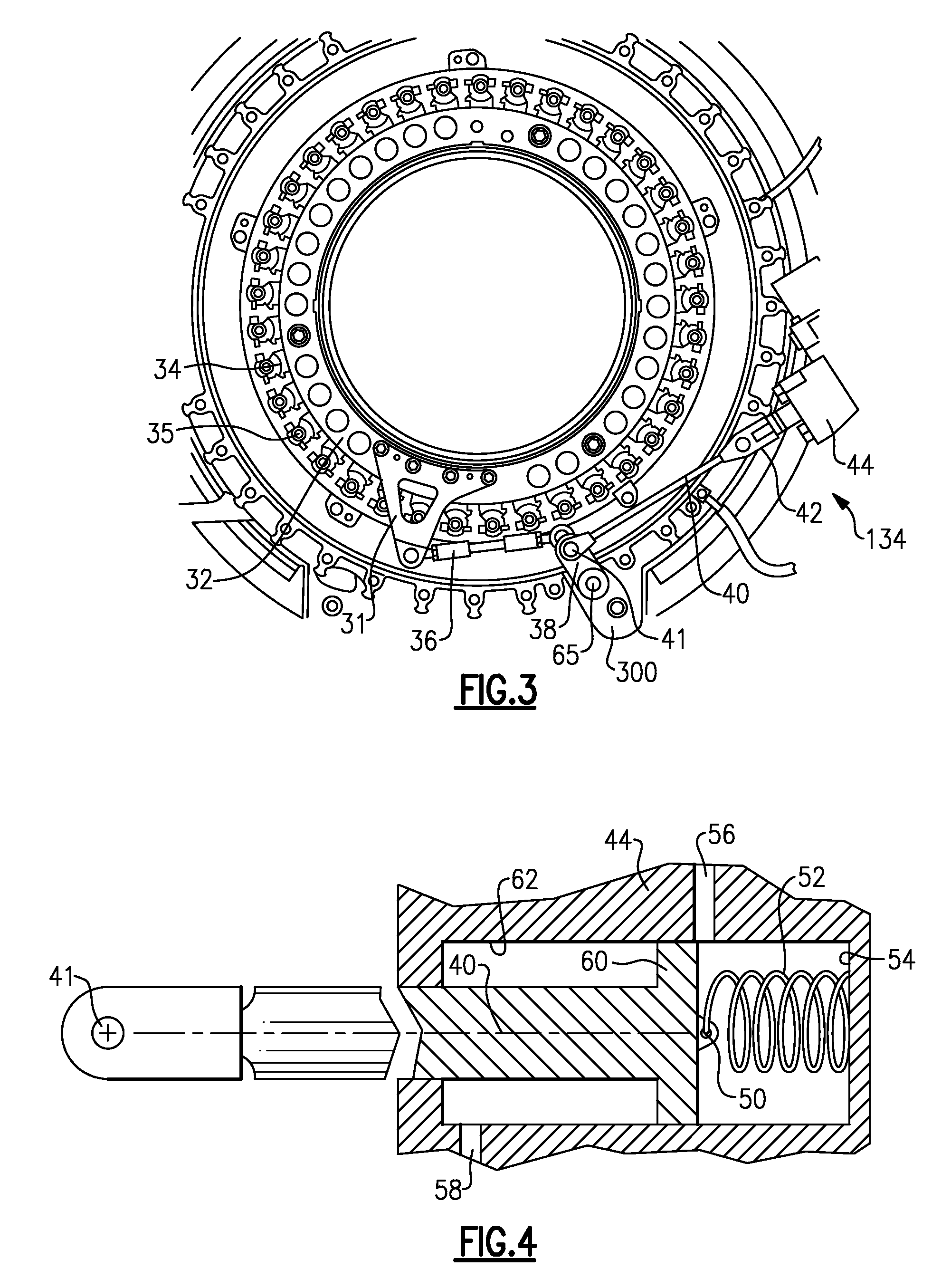
A variable vane system includes a plurality of vanes each being pivotal about an axis. A mechanical linkage drives the plurality of vanes to rotate about the axis. The mechanical linkage includes a ring gear to rotate, and in turn drive the plurality of vanes. There is at least one rod to drive the ring gear to rotate. The rod is driven by a hydraulic servo motor. A spring bias force is provided in the mechanical linkage to resist either translational or rotational oscillation.

Description

BACKGROUND OF THE INVENTION[0001]This application relates to a mechanical linkage for driving a compressor inlet guide vane system for gas turbine engines, wherein a spring preload is included into the mechanical linkage.[0002]Gas turbine engines include a compressor which compresses air and delivers it into a combustion section where it is mixed with fuel and burned. Products of this combustion pass downstream over a turbine section, driving turbine rotors to provide power to the gas turbine engine.[0003]Inlet guide vanes typically control the flow of air to the compressor section. Variable vane systems are known. In such systems, an angle of incidence provided by the vanes, for guiding the air to the compressor, is varied depending upon the amount of air that is to be delivered to the compressor.[0004]In one such system, a ring gear is driven to rotate through a mechanical linkage including a plurality of rods, and a hydraulic motor for driving the rods. The ring gear drives a plu...

Claims


Application Information

Patent Timeline
IPC IPC(8): F03B3/18
CPCF01D17/165F01D17/26F01D17/20
Inventor DUONG, LOC QUANGHU, XIAOLAN
Owner HAMILTON SUNDSTRAND CORP
Learn More