
Waveguide Orthomode Transducer

a transducer and waveguide technology, applied in the direction of waveguides, electrical devices, coupling devices, etc., can solve the problems of increasing the number of frequency bands covered by direct broadcast satellites

Active Publication Date: 2011-05-12
WISTRON NEWEB
View PDF6 Cites 10 Cited by
  • Summary
  • Abstract
  • Description
  • Claims
  • Application Information

AI Technical Summary

Benefits of technology

[0009]The present invention discloses a waveguide orthomode transducer including a waveguide comprising a first waveguide portion and a second waveguide portion placed along a transmission direction of radio signals, the size of an aperture of the second waveguide portion smaller than the size of an aperture of the first waveguide portion, a first probe disposed at a first position, a second probe disposed at a second position, a third probe disposed at a third position, and a fourth probe disposed at a fourth position, wherein at least two of the first position, the second position, the third position, and the fourth position are located in the same plane perpendicular to the transmission direction of the radio signals.

Problems solved by technology

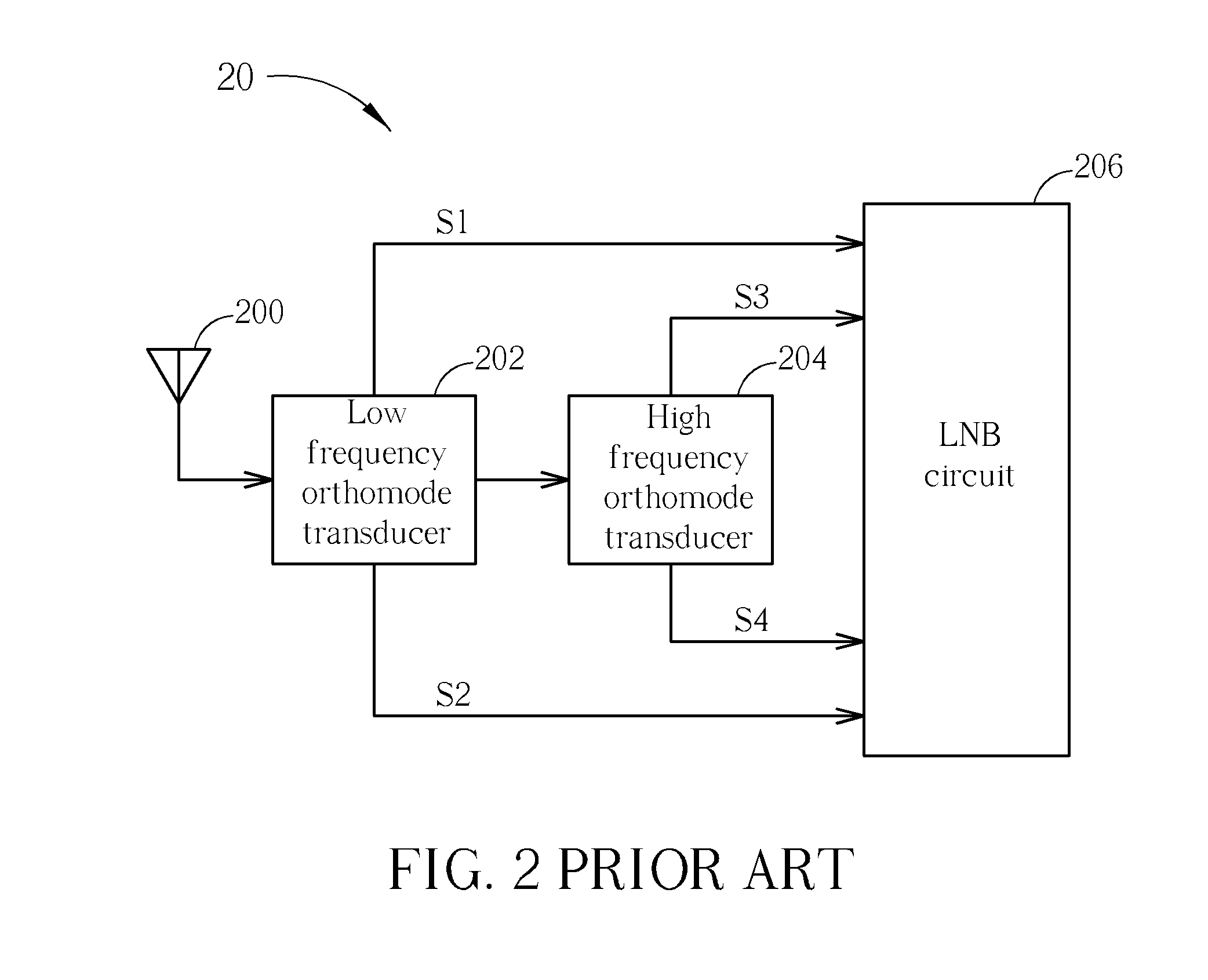
With the growth of the needs to satellite television, the number of frequency bands covered by the direct broadcast satellite is increasing, and the prior art single-band LNBF is not sufficient anymore.
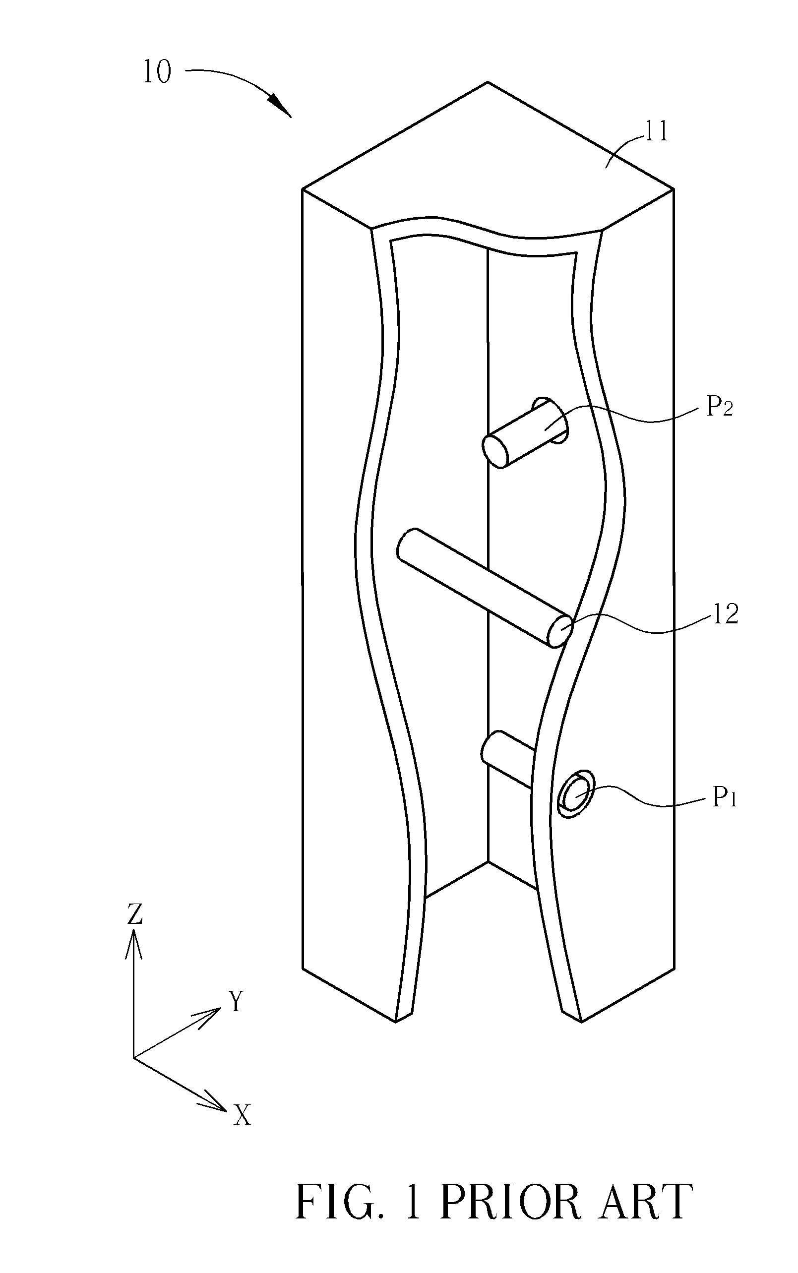
If these higher-order mode excitation signals are transmitted to the antenna, the high-frequency radiation patterns will be severely distorted.
Considering the above flaws, the orthomode transducer 10 is not feasible for the dual-band LNBF 20, which possibly results in a downgrade effectiveness of the LNBF 20 when receiving the high frequency satellite signals, and hence affects the playing quality of a satellite television.

Method used


Image

  • Waveguide Orthomode Transducer
  • Waveguide Orthomode Transducer
  • Waveguide Orthomode Transducer

Examples


Embodiment Construction

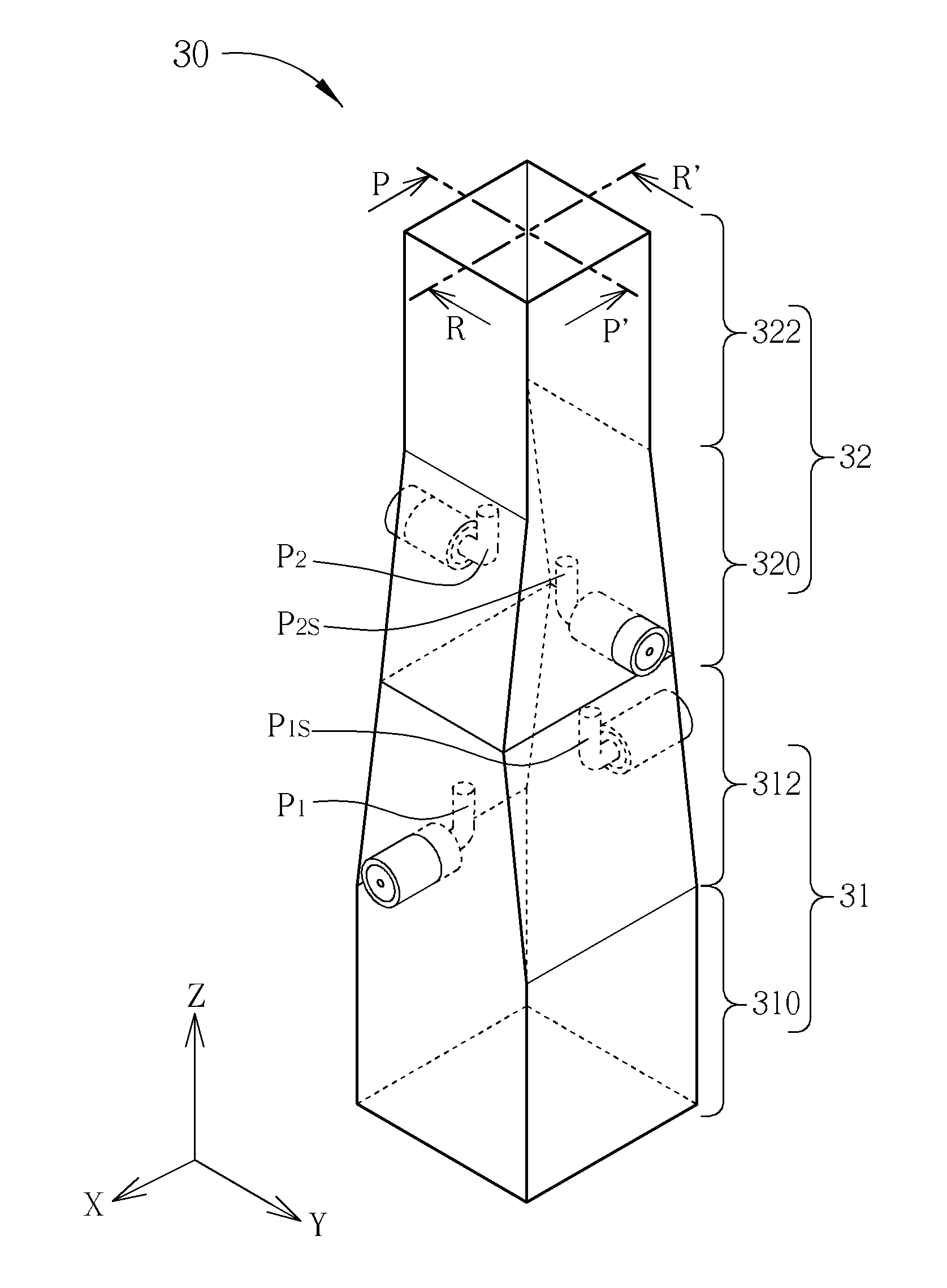
[0031]Please refer to FIG. 3. FIG. 3 is a half longitudinal sectional view of an orthomode transducer 30 according to an embodiment of the present invention. The orthomode transducer 30 is a waveguide orthomode transducer, feasible for a dual-band LNBF as an orthomode transducer for low frequency band, which is connected with an antenna at one end and an orthomode transducer for high frequency band at the other end. The orthomode transducer 30 comprises waveguide portions 31 and 32, and probes P1, P1S, P2, and P2S. In practice, the orthomode transducer 30 is a complete waveguide with various thickness of conducting walls; for clarity, in FIG. 3 the waveguide is segmented into the waveguide portion 31 and the waveguide portion 32. The waveguide portion 31 and the waveguide portion 32 are formed by conducting walls with different thickness respectively. The probes P1 and P2 are utilized as the output ports to output low frequency radio signals transmitted in the orthomode transducer 3...


PUM


Abstract

A waveguide orthomode transducer includes a waveguide including a first waveguide portion and a second waveguide portion placed along a transmission direction of radio signals, the size of an aperture of the second waveguide portion smaller than the size of an aperture of the first waveguide portion, a first probe disposed at a first position, a second probe disposed at a second position, a third probe disposed at a third position, and a fourth probe disposed at a fourth position, wherein at least two of the first position, the second position, the third position, and the fourth position are located in the same plane perpendicular to the transmission direction of the radio signals.

Description

BACKGROUND OF THE INVENTION[0001]1. Field of the Invention[0002]The present invention relates to a waveguide orthomode transducer, and more particularly, to a dual-band waveguide orthomode transducer.[0003]2. Description of the Prior Art[0004]Satellite communication is distinguished in wide coverage and terrestrial interference avoidance, and is widely used in military, probe, and commercial communication services, such as satellite navigation, satellite voice broadcasting, and satellite television broadcasting. A prior art satellite communication receiver consists of a dish reflector and a low noise block down-converter with feedhorn (LNBF); the LNBF is disposed on the focus of the dish reflector, receiving radio signals reflected via the dish reflector, down-converting the radio signals to middle band, and then transmitting the radio signals to a backend satellite signal processor for signal processing, enabling the playing of satellite television programs.[0005]A single-band LNBF...

Claims


Application Information

Patent Timeline
Patent Type & Authority Applications(United States)
IPC IPC(8): H01P3/12
CPCH01P1/161
Inventor LAN, I-CHINGLAI, CHUNG-MINHUANG, CHANG-HSIU
Owner WISTRON NEWEB
Learn More