
Partial Discharge Resistant Motor Slot Insulation

a technology of partial discharge and motor slot, which is applied in the direction of windings, electrical appliances, dynamo-electric machines, etc., can solve the problems of void discharge, deterioration of insulation, and more likely to be discharged

Inactive Publication Date: 2011-05-12
BAKER HUGHES INC
View PDF15 Cites 8 Cited by
  • Summary
  • Abstract
  • Description
  • Claims
  • Application Information

AI Technical Summary

Benefits of technology

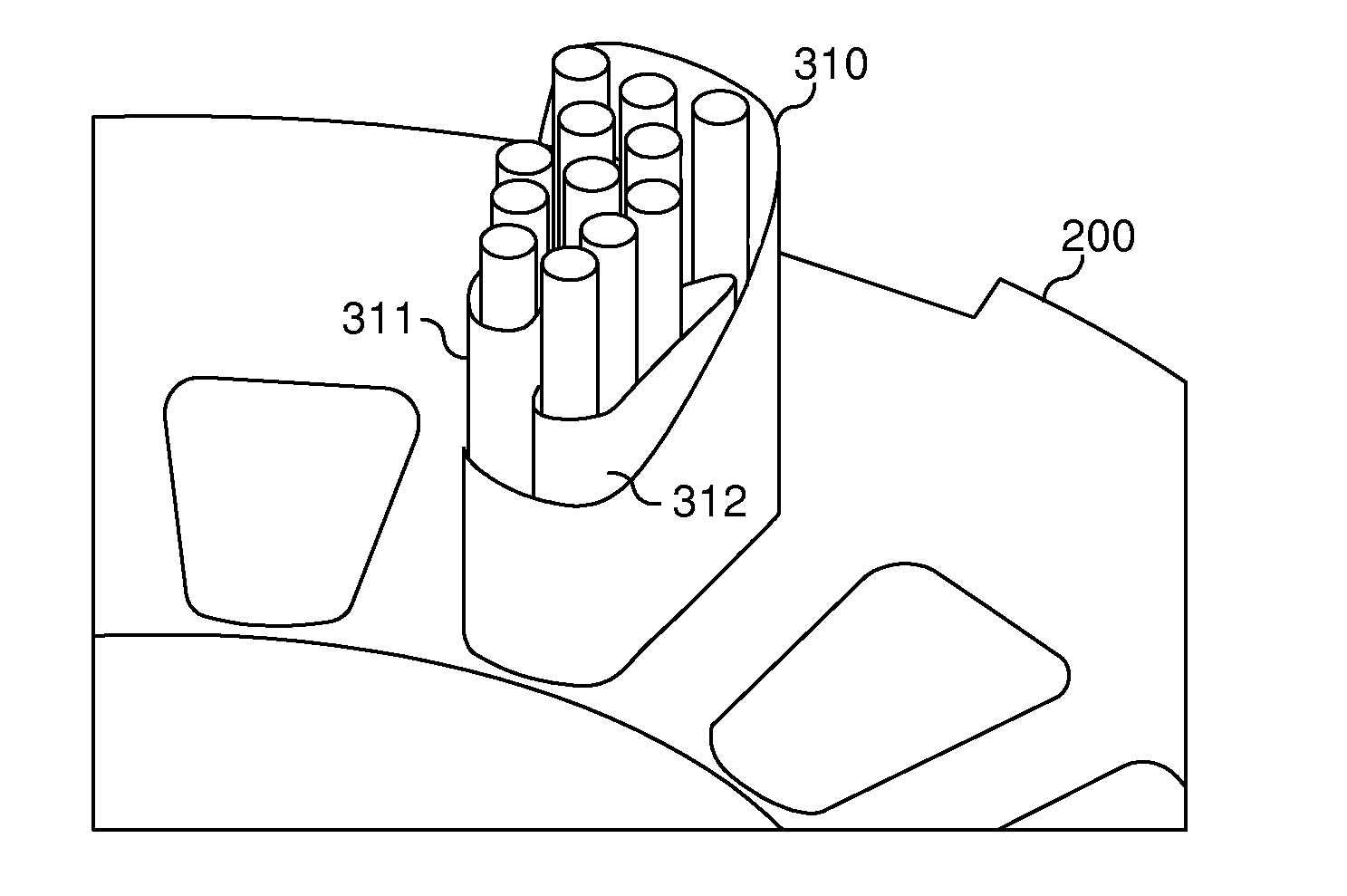
The insulating barriers within each passageway may be separate from or integral to the slot liner. If the insulating barriers are separate from the slot liner, they may, for example, comprise individual tubular insulators that are positioned within the slot liner. The slot liner and / or insulating barriers may be formed by extrusion, spiral-winding, or other means. If the insulating barriers are integral to the slot liner, they may, for instance, be extruded. The insulating barriers may be located within the slot liner to position a first set of wire turns (e.g., including a first wire turn having a maximum electrical potential) apart from a second set of wire turns (e.g., including a last wire turn having a minimum electrical potential) in order to provide further isolation of these sets of wire turns.

Problems solved by technology

If the wire were not insulated, the different turns of wire would be electrically coupled and would cause a short-circuit.
This breakdown occurs in small isolated areas in the insulator, often at weak points such as small gas bubbles, voids or inclusions in the insulator.
Any small inclusion or void in the high potential area of the insulation system is more likely to breakdown, creating a discharge in the void.
Partial discharges cause insulation to deteriorate, making further partial discharges more likely.
In random wound machines, it is not possible to ensure that wire turns are positioned to minimize voltage stress.
Eventually, partial discharges may cause enough insulation to deteriorate resulting in a complete insulation failure causing the motor to become non-functional and requiring the motor to be repaired or replaced.

Method used


Image

  • Partial Discharge Resistant Motor Slot Insulation
  • Partial Discharge Resistant Motor Slot Insulation
  • Partial Discharge Resistant Motor Slot Insulation

Examples


Embodiment Construction

One or more embodiments of the invention are described below. It should be noted that these and any other embodiments described below are exemplary and are intended to be illustrative of the invention rather than limiting.

As described herein, various embodiments of the invention comprise systems and methods for preventing partial discharge between turns of wire within a coil in an electric motor.

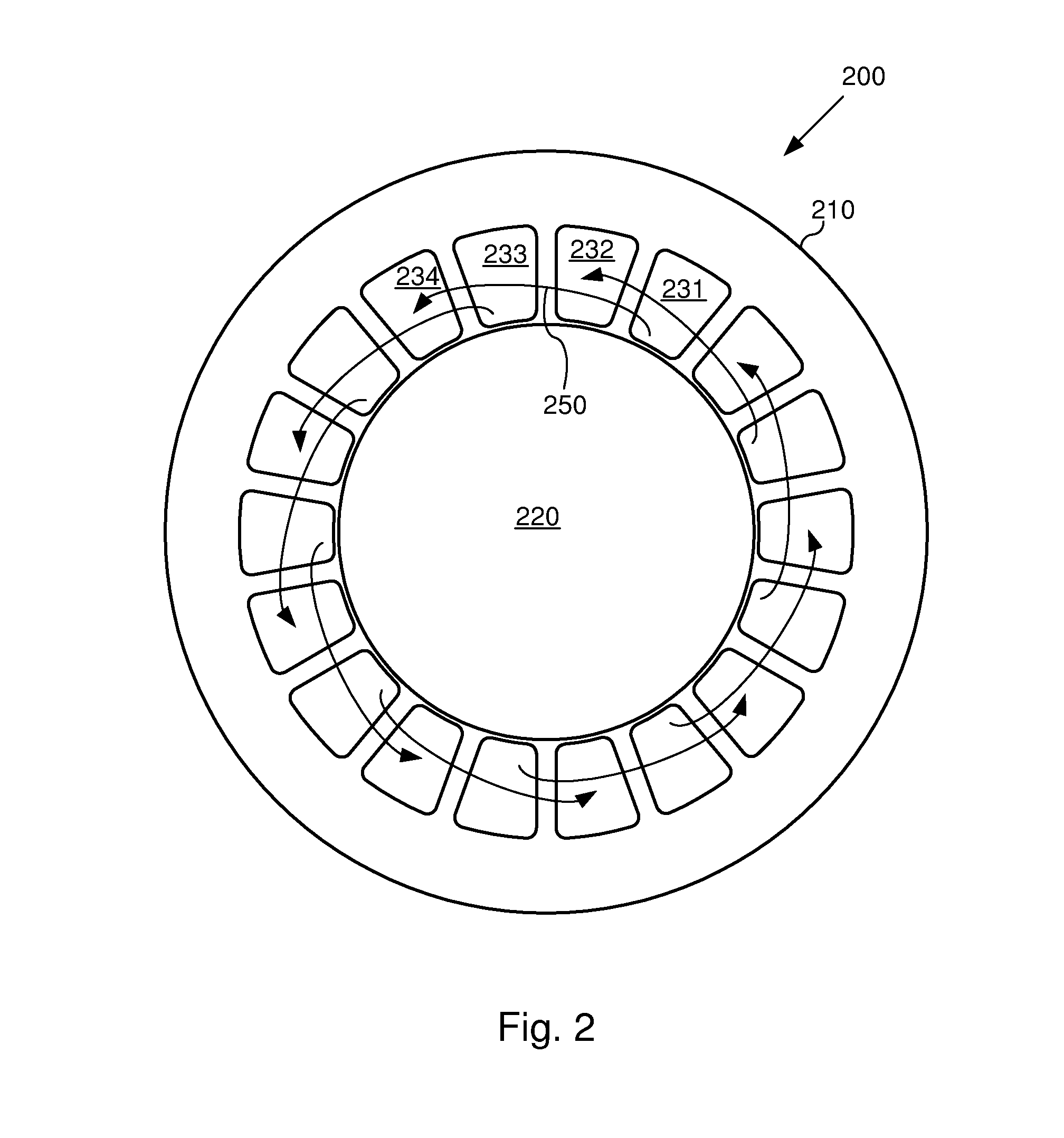
In one embodiment, a coil is constructed by threading wire through slots in a stator. Before the wire is threaded through the slots, an insulating slot liner is inserted into each slot. The slot liner will insulate all of the wires in the coil from the walls of the slot. Further, one or more tubular insulators are provided within the slot liner. Each of these additional tubular insulators will contain a different subset of the turns of wire that comprise the coil, and will insulate that subset of turns from other turns in the slot.

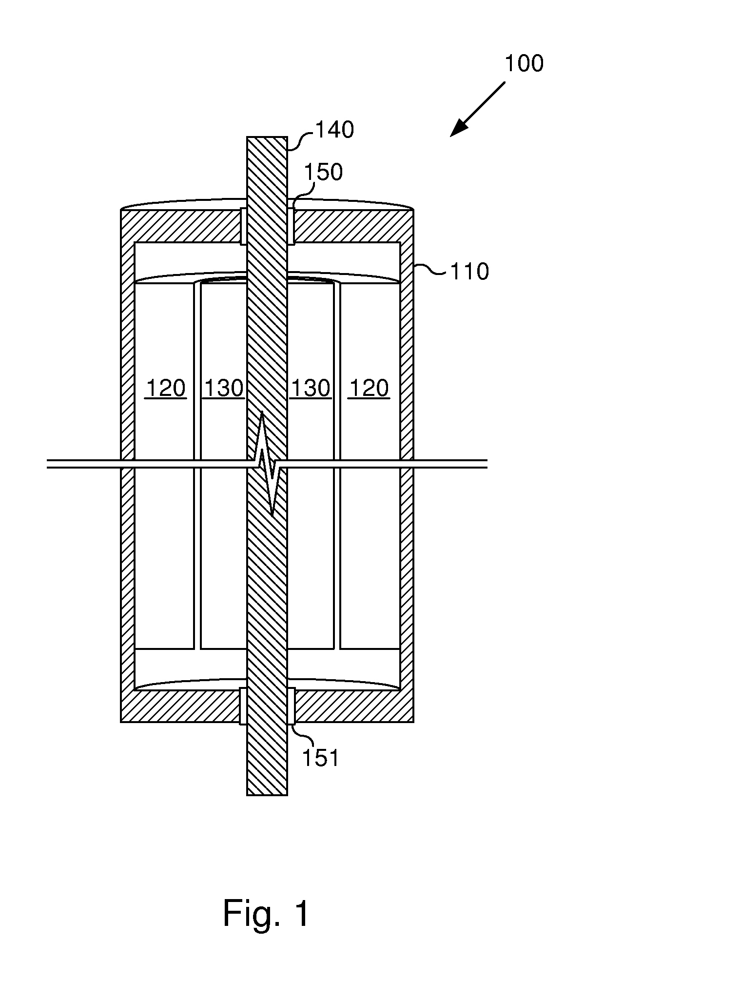
Referring to FIG. 1, a diagram illustrating the general struc...


PUM


Abstract

Systems and methods for reducing or preventing partial discharge between turns of a single coil within an electric motor by placing insulating barriers between different pluralities of wire turns in a single coil. One embodiment comprises an electric motor. The motor includes a rotor and a stator, where the stator has multiple coils of wire that are positioned in passageways in the stator to form electromagnets. Each wire coil has multiple wire turns, and insulating barriers are positioned between different sets of wire turns within the coil. In one embodiment, the stator includes a slot liner in each passageway to electrically isolate all of the wire turns in each coil from the walls of the passageway. The wire coils may be formed with wire that has an insulating coating which is separate from the insulating barriers.

Description

BACKGROUND1. Field of the InventionThe invention relates generally to random wound electric motors, and more particularly to systems and methods for preventing partial discharge between turns of wire within a coil in an electric motor. Additionally, the invention provides increased insulation strength between the highest potential turns and the ground wall.2. Related ArtA typical electric motor has two primary components: a rotor; and a stator. The stator is a stationary component, while the rotor is a movable component which rotates within the stator. Typically, in a DC motor, or in a permanent magnet motor, one or the other of these components has a permanent magnet, while the other uses coils of electrical wire to generate changing magnetic fields. In an AC induction motor or synchronous motor, a magnetic field is induced into the rotor. The interaction of the magnetic fields created by the stator and the rotor cause the rotor to rotate within the stator.The motor incorporates el...

Claims


Application Information

Patent Timeline
IPC IPC(8): H02K3/34
CPCH02K3/34
Inventor SHAVER, CLARK D.CAIN, SEAN A.
Owner BAKER HUGHES INC
Learn More