
Resilient clamp for holding a container by the neck

a technology for containers and clamps, applied in the field of clamps for holding containers by the neck, can solve the problems of increasing manufacturing costs and setting time, affecting the safety of workers,

Inactive Publication Date: 2011-05-12
SIDEL PARTICIPATIONS SAS
View PDF4 Cites 22 Cited by
  • Summary
  • Abstract
  • Description
  • Claims
  • Application Information

AI Technical Summary

Benefits of technology

[0007]It is therefore an object of the invention to provide a clamp of the one-piece type, having enough resilience to allow smooth clipping of a container neck during the transfer operations.
[0008]It is another object of the invention to provide a clamp of the one-piece type, suitable for safely gripping containers of different formats.

Problems solved by technology

However, clamps of that type have drawbacks, due to the important number of numerous moving parts they include, which not only increases their manufacturing costs and their setting time, but also creates problems of reliability due to wear and setting defaults.
Transfer devices do not work that way, though, for containers move along arc-of-circle paths and are transferred from one clamp to another in a tangential way, in a transfer area where the periphery of the two adjacent star wheels locally overlap.
More precisely, as the arms are not open when they come in contact with the container neck, the distance between the gripping jaws of the arms at the radial end thereof may be too short for the container to smoothly and easily force its way between the arms.
However such a solution is not satisfactory because, on the other hand, the angular opening of each gripping jaw should be set a maximum value to ensure sufficient—and therefore safe—enclosure of the container during its arc-of-circle path on the transfer wheel, along which path strong centrifugal forces apply, which tend to force the container out of the clamp.
One further and common drawback of the hereabove disclosed clamps of both types is that they do not (at least, not easily) adapt to several container formats, i.e. to different diameters of container necks.

Method used


Image

  • Resilient clamp for holding a container by the neck
  • Resilient clamp for holding a container by the neck
  • Resilient clamp for holding a container by the neck

Examples


Embodiment Construction

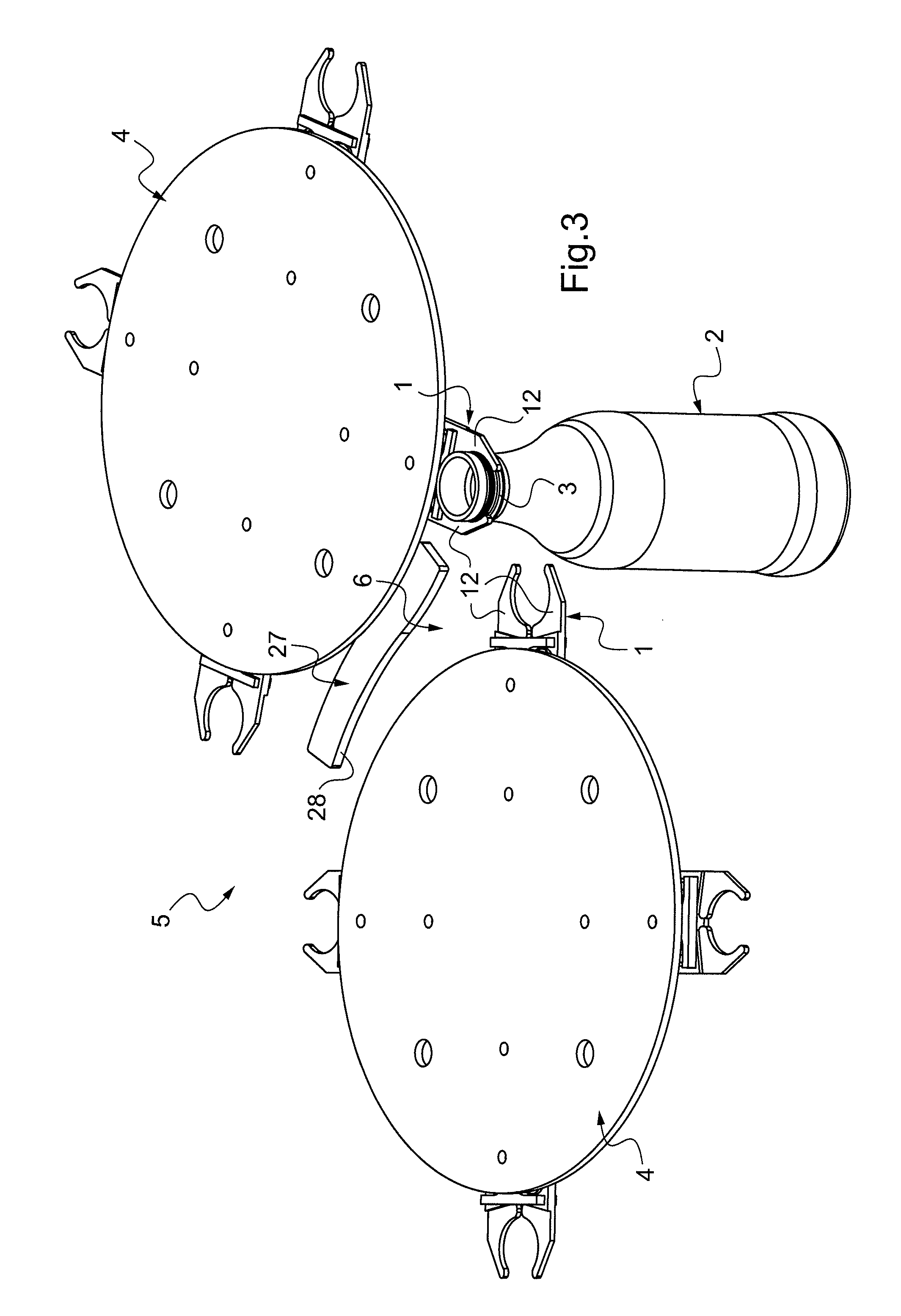
[0030]Turning now to the drawings, there is represented on FIG. 1 and FIG. 2 a clamp 1 for gripping and holding a container 2 by a neck 3. The clamp 1 is to be mounted at the periphery of a rotary container transfer device 4 of a container handling machine 5, such as a star wheel, as depicted on FIG. 3-7. More specifically, two adjacent star wheels 4 equipped with such clamps 1 are represented on FIG. 3-7, which rotate in conjunction and define arc-of-circle transfer paths converging in a transfer area 6 where the clamps 1 locally overlap to ensure proper transfer of the containers 2 from one star wheel 4 to the adjacent one. Operation of the star wheels 4 will be further disclosed hereinafter.

[0031]The clamp 1 is one-piece and made of a metallic or plastic material, such as stainless steel or resistant resin. The clamp 1 comprises an elongated central body 7 provided with a pair of holes 8 receiving screws for removably mounting the clamp 1 at the periphery of a star wheel 4. The b...


PUM


Abstract

Clamp (1) for holding a container (2) by a neck (3) in a container handling machine (5), said clamp comprising a body (7) for mounting the clamp (1) on a rotary support (4), and a pair of resilient arms (11) protruding sidewise from the body (7) and each provided with a gripping jaw (12), wherein each resilient arm (11) comprises:an inner section (13) extending along the body (7) and connected thereto at a first back end junction (16);an intermediate section (14) extending substantially parallel to the inner section (13) and connected thereto at a front end junction (17);an outer section (15), provided, at a front end, with a gripping jaw (12), and extending substantially parallel to the intermediate section (14) and connected thereto at a second back end junction (18).

Description

FIELD OF THE INVENTION[0001]The invention relates to the field of container handling, and more precisely to a clamp for holding a container by a neck in a container handling machine.BACKGROUND OF THE INVENTION[0002]Plastic containers, and especially plastic bottles, have a neck the dimensions of which are precisely defined and remain unchanged during the manufacturing operations. Most handling machines include transfer devices such as transfer wheels provided at their periphery with a plurality of neck grippers or clamps configured to receive and hold the containers by their necks.[0003]There exist several types of clamp designs. According to the most common design, the clamp comprises a pair of arms hinged with respect of each other, the angular position of which is controlled e.g. by cam means including a fixed cam path interacting with a movable cam follower provided on one of the arms, in such a way that when reaching a loading point the arms open to allow a container neck to be...

Claims


Application Information

Patent Timeline
IPC IPC(8): B65G47/86B25J15/00B65G47/74
CPCB65G47/847B65G47/908B65G2201/0247
Inventor SARDA, ERIC
Owner SIDEL PARTICIPATIONS SAS
Learn More