Spary device and operation method thereof
a technology of a spare device and a pump, which is applied in the field of spare device and an operation method thereof, can solve the problems that the supporting arm, the splash disk, and the splashing water would disadvantageously affect the atomization of the jetted water, affecting the fire extinguishing effect, and achieve the effect of reducing the pressure applied
- Summary
- Abstract
- Description
- Claims
- Application Information
AI Technical Summary
Benefits of technology
Problems solved by technology
Method used
Image
Examples
embodiment 1
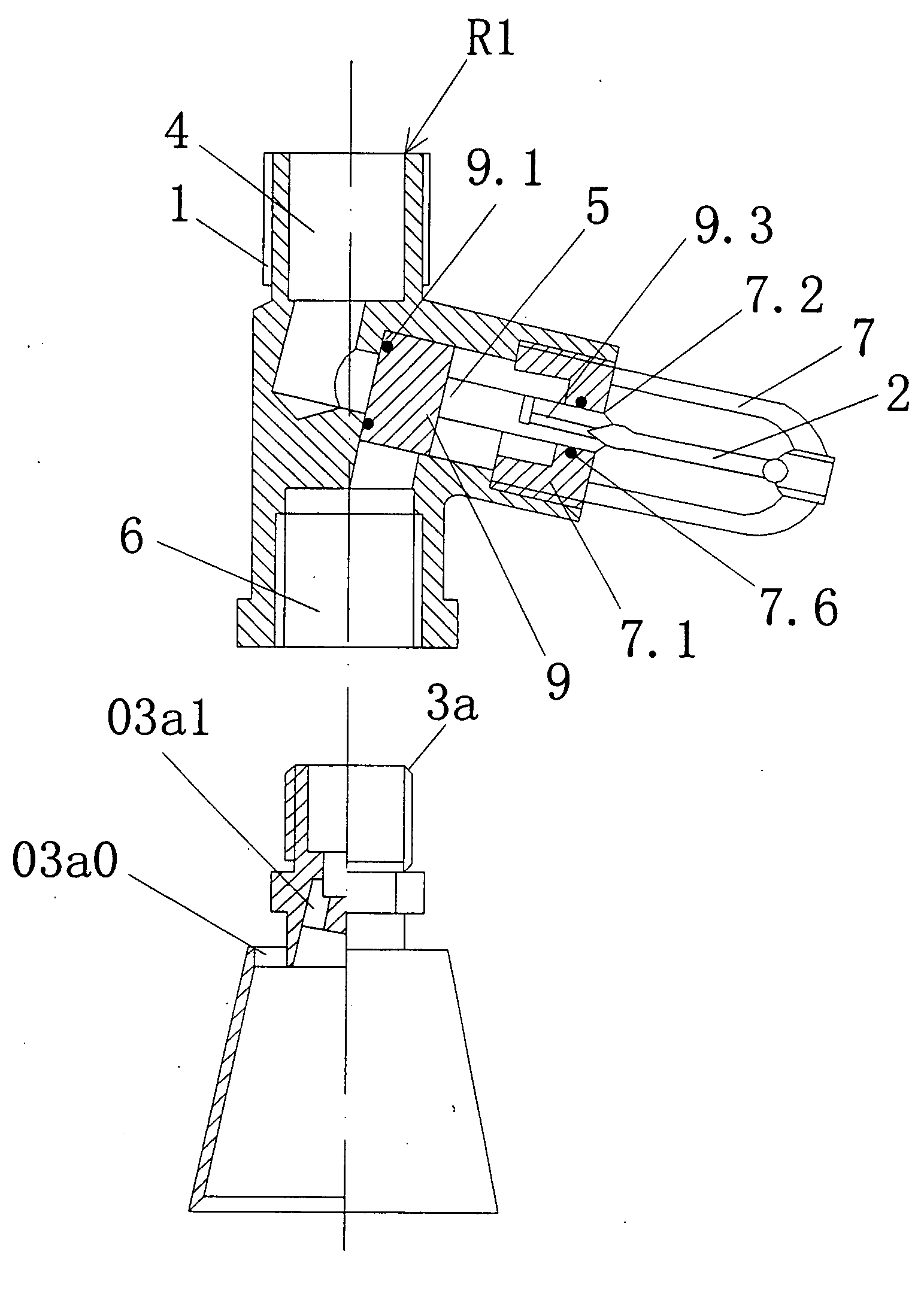
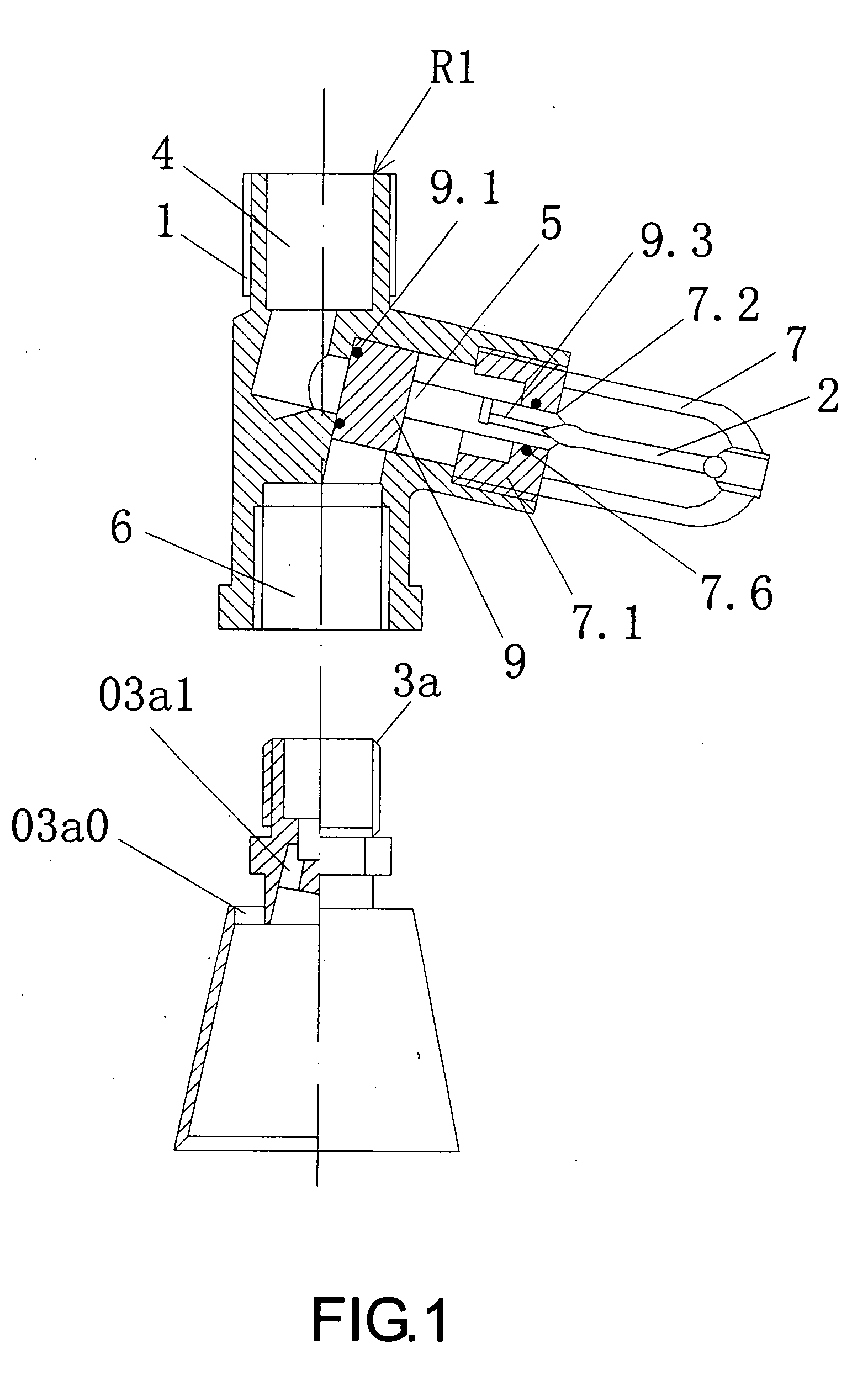
[0058]Referring to FIG. 1 of the drawings, in the present invention, the spray device according to embodiment 1 includes a normally closed valve R1 and a spray head 3a. The normally closed valve R1 is provided with a valve body 1, a thermal sensitive mechanism, a bracket 7 and a piston element 9. An outlet chamber 6 of the normally closed valve R1 is directly connected with the spray head 3a by thread.
[0059]The valve body 1 is provided with an inlet chamber 4, a control chamber 5 and the outlet chamber 6. The control chamber 5 is disposed between the inlet chamber 4 and the outlet chamber 6, the inner end of which is arranged to communicate with the inlet chamber 4 and the outlet chamber 6. The control chamber 5 is located at a lateral position of the outlet chamber 6, that is, an inclination angle (the inclination angle may less than, equal to, or larger than 90 degree) would be formed by intersecting between the axis line of the control chamber 5 and the axis line of the outlet ch...
embodiment 2
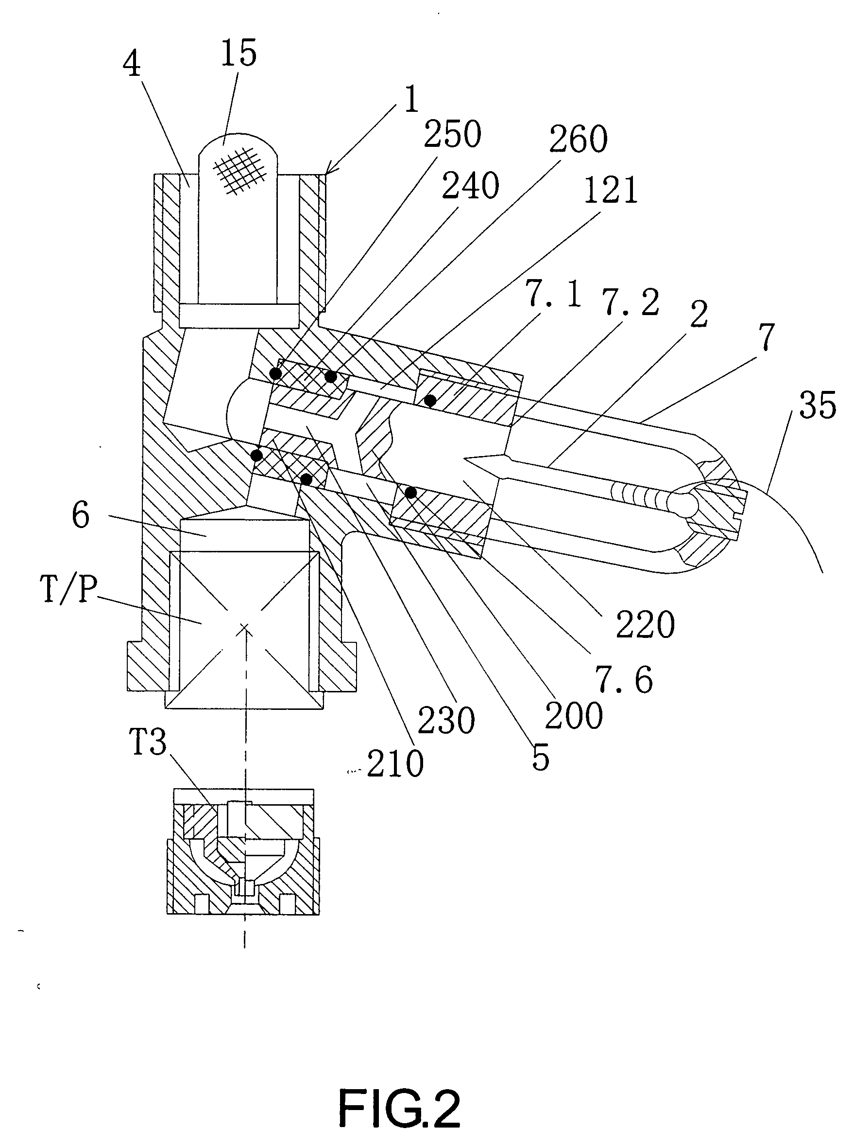
[0062]Referring to FIG. 2 of the drawings, the spray device according to this embodiment includes the normally closed valve R1 and the spray head. The spray head in the embodiment may be a spray head P in which an atomizing core spray nozzle T is provided. The normally closed valve R1 includes the valve body 1, a piston element 200, the thermal sensitive mechanism (being the separate thermal sensitive element 2) and the bracket 7. The valve body 1 is provided with the inlet chamber 4, the control chamber 5 and the outlet chamber 6. The inlet chamber 4 is connected to an outer pressure flow source, and provided with the filter 15 (which may be provided according to the requirement). The outlet chamber 6 communicates with the spray head P or atomizing core spray nozzle T by a thread connection. The control chamber 5 is provided at a lateral position between the inlet chamber 4 and the outlet chamber 6. A piston element 200 is provided in the control chamber 5. The piston element 200 s...
embodiment 3
[0067]Referring to FIG. 3 of the drawings, this embodiment is similar to embodiment 1, but the differences are that: the valve body 1 of the normally closed valve R2 of the spray device is a multi-way body, the valve body 1 is provided with 2 big-hole outlet chambers 6 (the number of the outlet chambers 6 may be determined according to the requirement), the control chamber 5 is perpendicular to the outlet chambers 6, and the control chamber 5 is provided at the lateral position of the outlet chambers 6. The filter 15 (which may be provided according to the requirement) may be provided in the inlet chamber 4. A spring 10 may be provided between the piston element 9 and the end cover 7.1, one end thereof being in contact with the end cover 7.1, and the other end thereof being in contact with the piston element 9. The spring 10 facilitates the press and return of the piston element 9. One outlet chamber 6 at the lower portion of the valve body 1 is directly connected to a spray head 3C...
PUM
 Abstract
Description
Claims
Application Information
 - R&D
- Intellectual Property
- Life Sciences
- Materials
- Tech Scout
- Unparalleled Data Quality
- Higher Quality Content
- 60% Fewer Hallucinations
Browse by: Latest US Patents, China's latest patents, Technical Efficacy Thesaurus, Application Domain, Technology Topic, Popular Technical Reports.
© 2025 PatSnap. All rights reserved.Legal|Privacy policy|Modern Slavery Act Transparency Statement|Sitemap|About US| Contact US: help@patsnap.com


