Latch system and a vehicle
- Summary
- Abstract
- Description
- Claims
- Application Information
AI Technical Summary
Benefits of technology
Problems solved by technology
Method used
Image
Examples
Embodiment Construction
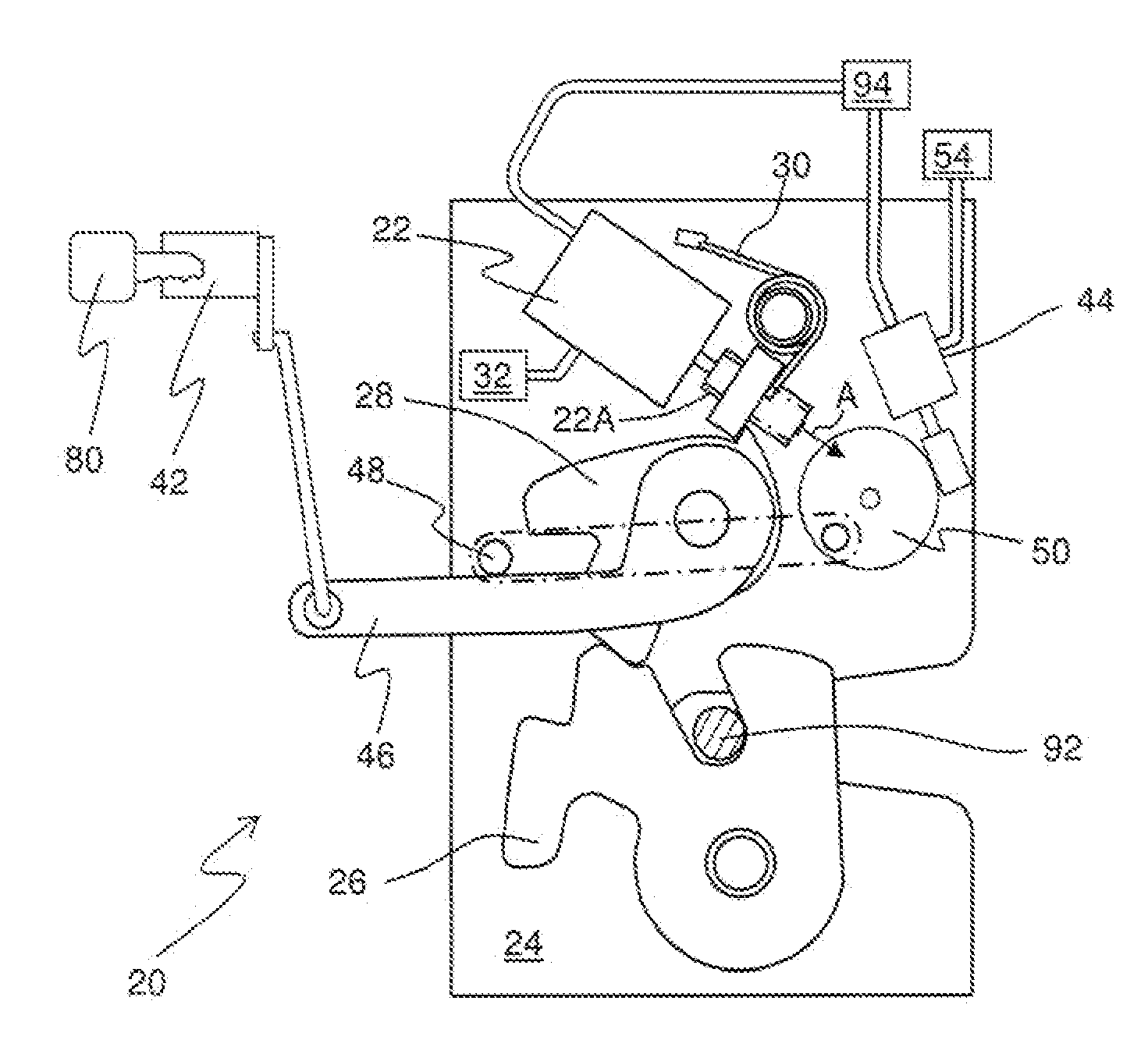
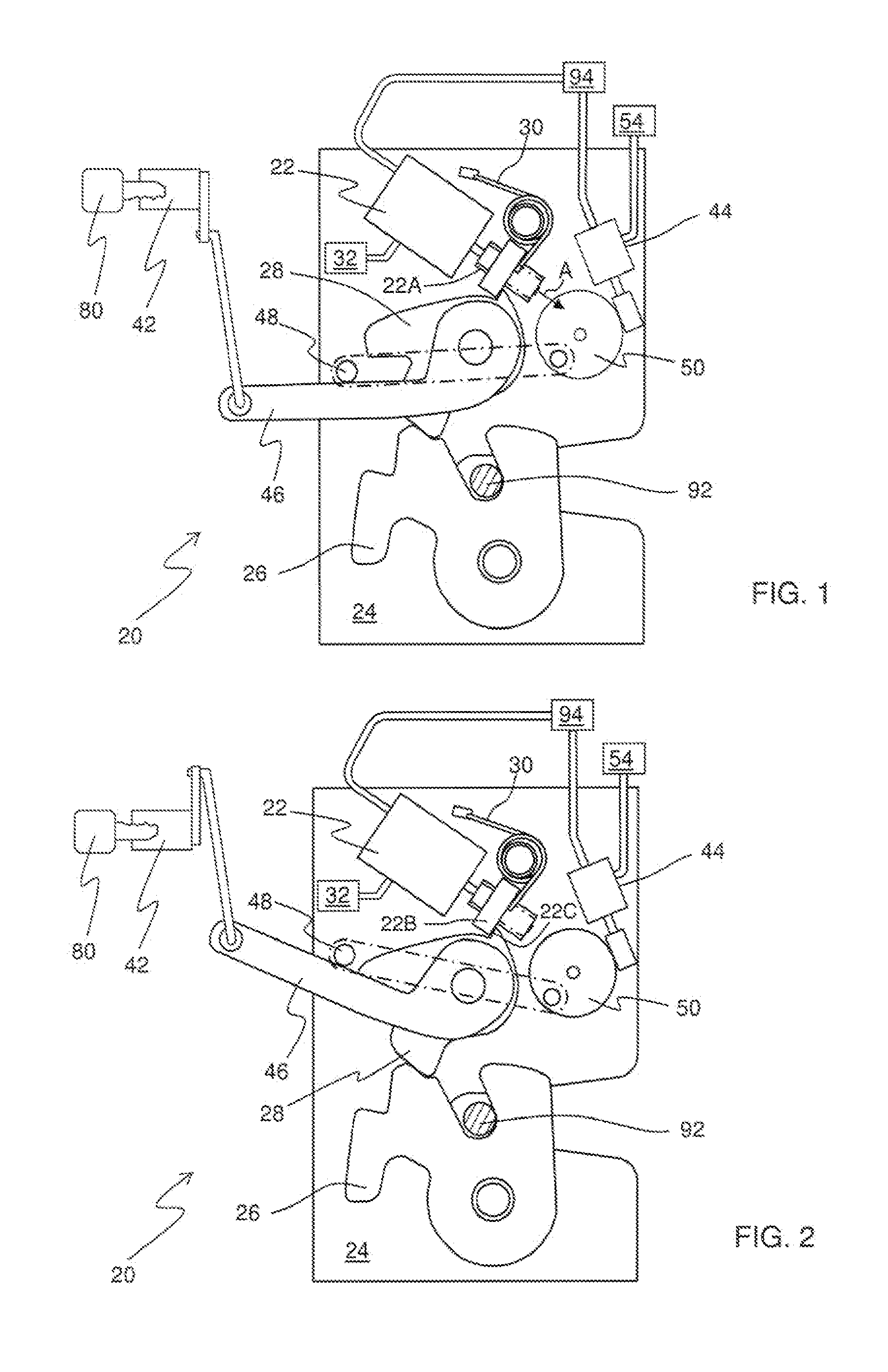
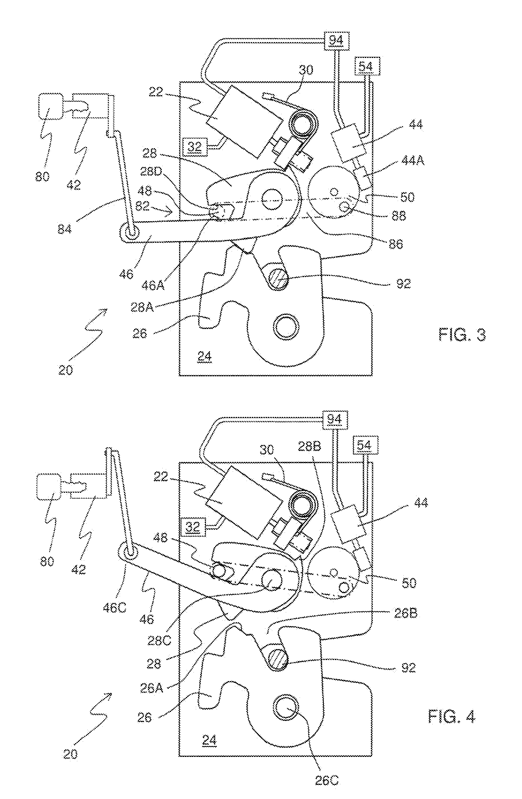
[0015]With reference to FIGS. 1 to 4, there is shown a first latch 20 having a latch chassis 24 upon which is mounted a latch bolt in the form of a rotating claw 26. The rotating claw 26 releasably retains a striker 92. Typically, the first latch 20 may be mounted on a vehicle door, and the striker 92 may be mounted on the associated door aperture of the vehicle, typically on a B-post or a C-post of a vehicle. As shown in FIG. 1, the rotating claw 26 is in a closed position, being held in that position by a pawl 28. Rotation of the pawl 28 from the FIG. 1 position in a clockwise direction about a pivot 28C to the FIG. 4 position causes an abutment 28A to disengage from an abutment 26A, thereby allowing the rotating claw 26 to rotate in a clockwise direction about a pivot 26C and release the striker 92 from the mouth 26B of the rotating claw 26. FIG. 4 shows the moment at which the abutment 28A has been disengaged from the abutment 26A but just prior to the moment at which striker 92...
PUM
 Abstract
Description
Claims
Application Information
 - R&D
- Intellectual Property
- Life Sciences
- Materials
- Tech Scout
- Unparalleled Data Quality
- Higher Quality Content
- 60% Fewer Hallucinations
Browse by: Latest US Patents, China's latest patents, Technical Efficacy Thesaurus, Application Domain, Technology Topic, Popular Technical Reports.
© 2025 PatSnap. All rights reserved.Legal|Privacy policy|Modern Slavery Act Transparency Statement|Sitemap|About US| Contact US: help@patsnap.com


