Planar grooved power inductor structure and method

a technology of power inductor and groove, which is applied in the direction of inductance, magnets, magnetic bodies, etc., can solve the problems of complex process automation, insufficient efficiency of winding wire to form toroidal coil, and inability to meet the needs of the user, and achieves ultra-low resistance and high inductance.

Active Publication Date: 2011-05-12
ALPHA & OMEGA SEMICON LTD
View PDF30 Cites 4 Cited by
  • Summary
  • Abstract
  • Description
  • Claims
  • Application Information

AI Technical Summary

Benefits of technology

[0058]Many advantages to such a planar inductor configuration may clearly seen. The planar structure of the inductor allows the inductor to be easily stackable. The thickness of the inductor is a function of the groove depth. By forming grooves of a sufficient depth, and vias of a sufficient diameter, the inductor can achieve ultra-low resistance. Also, the vias, which connect the top and bottom sides of the inductor coil, may be formed away from the edges of the ferrite substrate, which allows the ferrite material to form a closed magnetic loop around the inductor coils. A closed magnetic loop greatly increases the inductance per unit area.
[0060]By way of example, an IC chip can be stacked on top of the inductor 200, with the additional through vias 109 providing electrical routing from the IC chip to the bottom of the inductor 200. The stacked IC chip with inductor 200 can be mounted on a circuit board with all the necessary electrical routing available on the bottom of the inductor 200. Again, the planar structure of the inductor allows for stacking to be easily accomplished.
[0095]The inductors of the present invention have planar structure and with ultra-low resistance, high inductance per unit area and compatible with stacked Power-IC on Inductor concept. The methods for making the inductors of the present invention are low-cost and can be implemented with a single magnetic core layer.

Problems solved by technology

In recent years, the miniaturization of inductors has been an issue in miniaturization of power converters.
However, winding wire is not the most efficient process to form a toroidal coil.
Typical toroidal coil inductors require “feeding” of the wire through a center hole in a doughnut shaped ferrite core, which is a complex process to automate.
However, the thickness of the inductor coil conductors is limited to the thickness of the conductive layer deposited on the magnetic insulating substrate.
Many conventional power inductors are not planar, have relatively high resistance due to the limited thickness (size) of the inductor conductors, do not have a completely closed magnetic loop or do not incorporate a means of connecting other components in a stacked configuration (which minimizes the overall area).

Method used


Image

  • Planar grooved power inductor structure and method
  • Planar grooved power inductor structure and method
  • Planar grooved power inductor structure and method

Examples


Embodiment Construction

[0054]Although the following detailed description contains many specific details for the purposes of illustration, anyone of ordinary skill in the art will appreciate that many variations and alterations to the following details are within the scope of the invention. Accordingly, the exemplary embodiments of the invention described below are set forth without any loss of generality to, and without imposing limitations upon, the claimed invention.

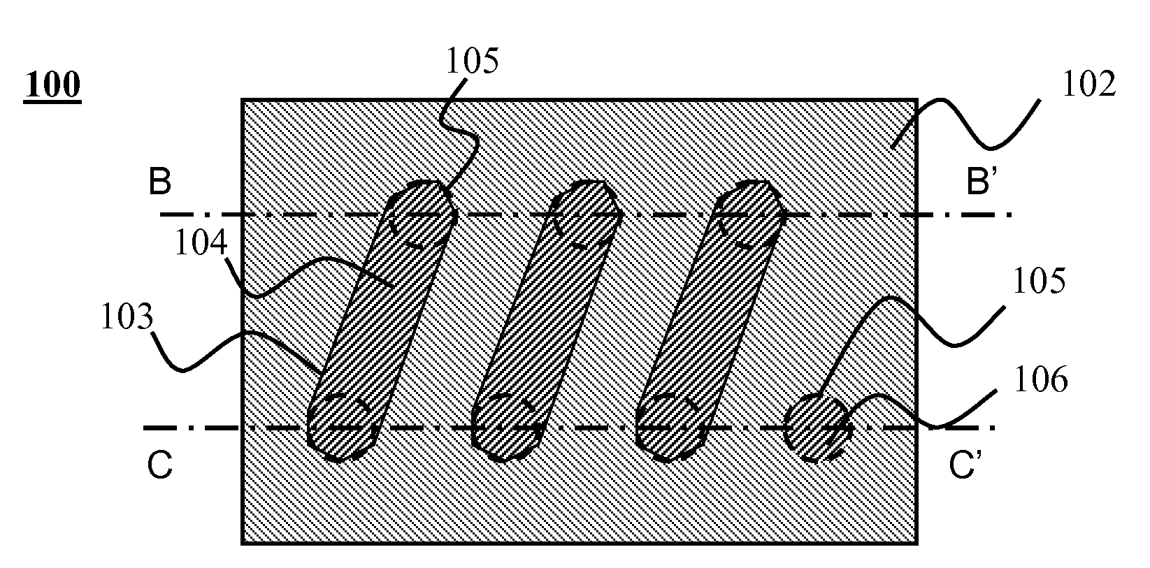
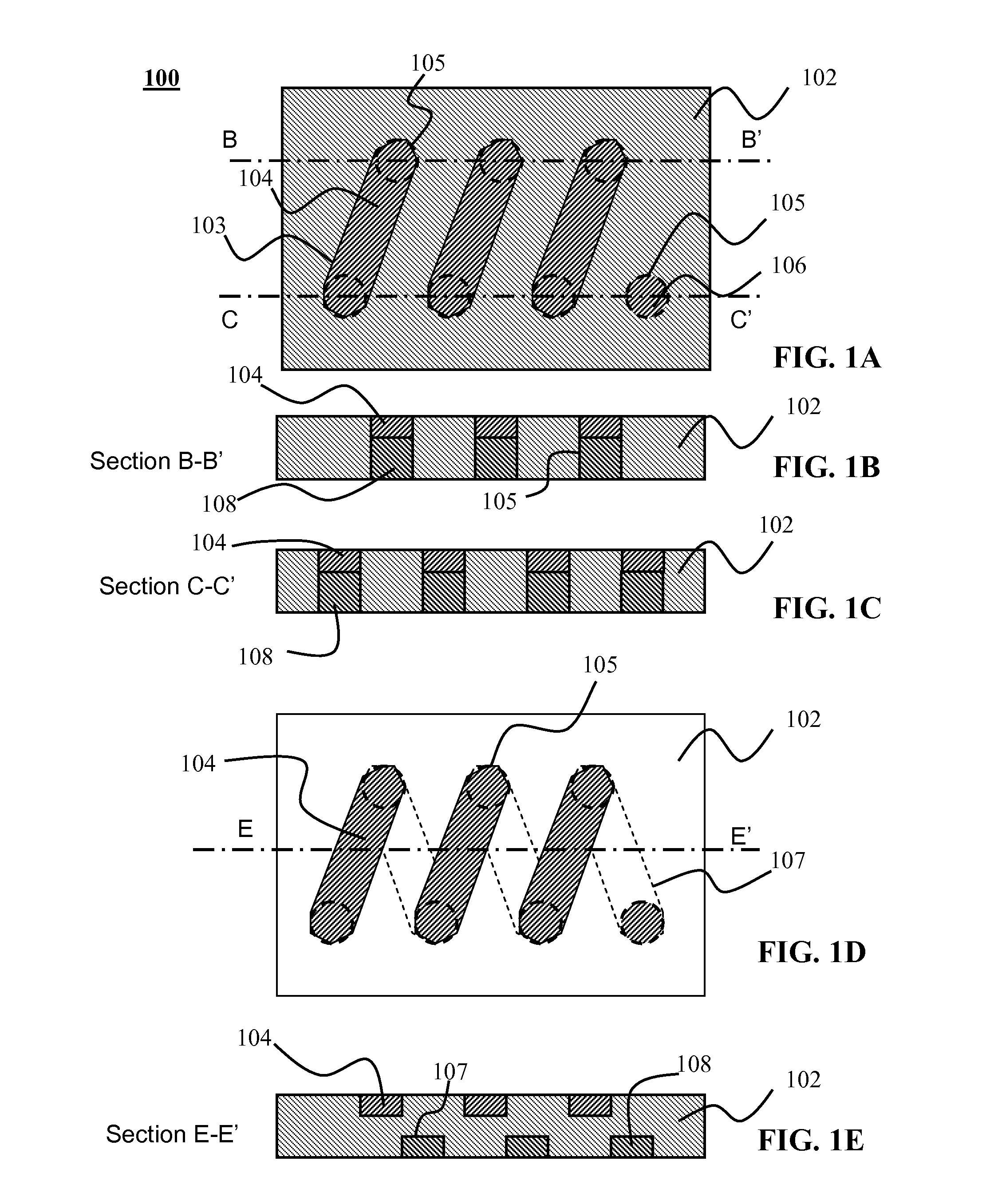
[0055]As shown in FIGS. 1A-1E, a discrete power inductor 100 according to an embodiment of the present invention may include a ferrite core in the form of a single ferrite layer 102 with a pattern of one or more parallel grooves 103 on its top surface, which are filled with conductive material 104 to form a set of top electrodes. The inductor 100 also includes patterned grooves 107 on its bottom surface, which are filled with conductive material 108 to form bottom electrodes as shown in FIG. 1D. The inductor 100 also includes through vias 10...


PUM

PropertyMeasurementUnit
temperatureaaaaaaaaaa
thicknessaaaaaaaaaa

Abstract

An inductor may include a planar ferrite core. A first group of one or more grooves is formed in a first side of the ferrite core. A second group of two or more grooves is formed in a second side of the ferrite core. The grooves in the first and second groups are oriented such that each groove in the first group overlaps with two corresponding grooves in the second group. A first plurality of vias communicates through the ferrite core between the first and second sides of the ferrite core. Each via is located where a groove in the first group overlaps with a groove in the second group. A conductive material is disposed in the first and second groups of grooves and in the vias to form an inductor coil.

Description

PRIORITY CLAIM[0001]This application is a divisional application of U.S. application Ser. No. 12 / 165,423 filed Jun. 30, 2008, the entire disclosures of which are incorporated herein by reference.FIELD OF THE INVENTION[0002]This invention generally relates to discrete power inductor and more particularly to low-cost and ultra-small discrete power inductors.BACKGROUND OF THE INVENTION[0003]In recent years, electronic information equipment, especially various portable types of electronic information equipment, have become remarkably widespread. Most types of electronic information equipment use batteries as power sources and include built-in power converters such as DC-DC converters. In general, a power converter is constructed as a hybrid module in which individual parts of active components, such as switching elements, rectifiers and control ICs, and passive elements, such as inductors, transformers, capacitors and resistors, are located on a ceramic board or a printed board of plast...

Claims


Application Information

Patent Timeline
Patent Type & Authority Applications(United States)
IPC IPC(8): H01F7/06
CPCH01F1/344H01F17/0033Y10T29/4902H01F2017/002H01F41/046
Inventor HEBERT, FRANCOISFENG, TAOLU, JUN
Owner ALPHA & OMEGA SEMICON LTD
Why Eureka
Try Eureka