
System and method for an intervertebral implant assembly

a technology of intervertebral implants and systems, applied in the field of systems and methods for intervertebral implants, can solve the problems of long operating procedures for attaching rods and inserting intervertebral implants, and the disorder of spine, and achieve the effect of promoting vertebral fusion

Active Publication Date: 2011-05-05
KIC VENTURES LLC
View PDF22 Cites 82 Cited by
  • Summary
  • Abstract
  • Description
  • Claims
  • Application Information

AI Technical Summary

Benefits of technology

[0012]Among the advantages of this invention may be one or more of the following. The inserter attaches to the implant without the use of threads or screws through the implant. Once in the body, the implant acts as a spacer for intervertebral decompression and promotes vertebral fusion with the use of bone growth materials. Bone growth material can be inserted in the second through opening through the open back end after the implant has been inserted between the adjacent vertebras.

Problems solved by technology

However, disorders of the spine occur when one or more of these spine structures are abnormal.
However, the operating procedure for attaching the rods and inserting the intervertebral implant is usually long.

Method used


Image

  • System and method for an intervertebral implant assembly
  • System and method for an intervertebral implant assembly
  • System and method for an intervertebral implant assembly

Examples


Embodiment Construction

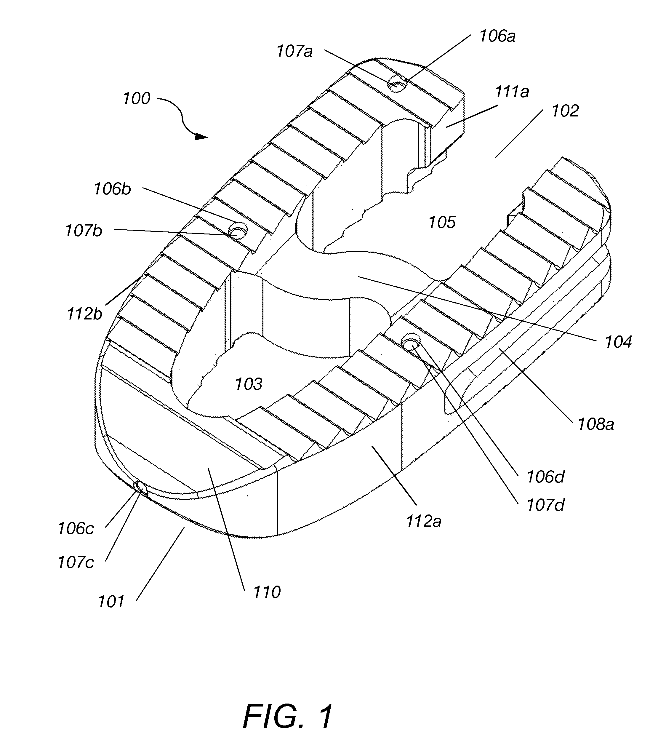
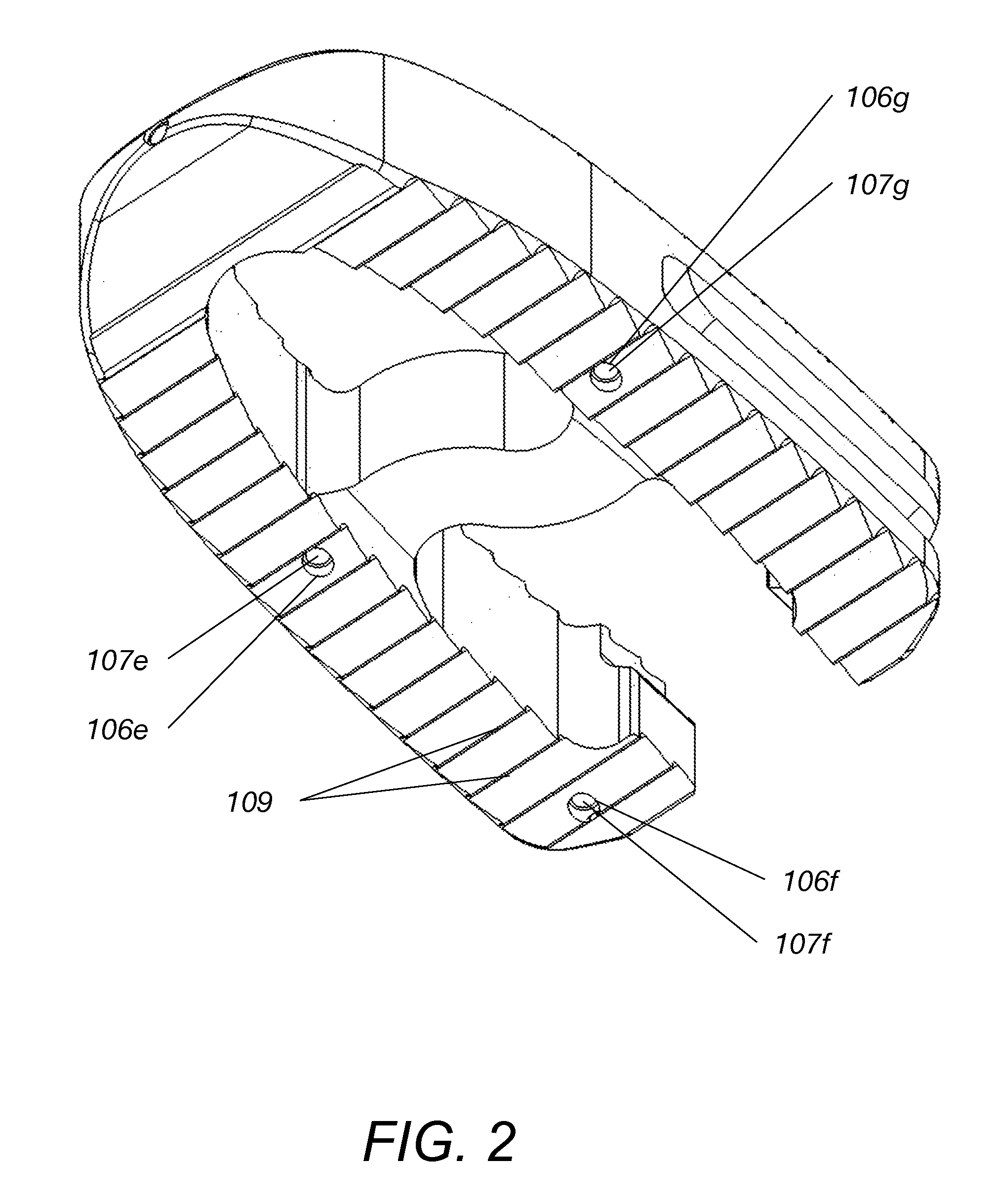
[0034]Referring to FIG. 7, implant assembly 99 includes an interbody implant 100 used for spinal fusion procedures and a unique inserter 120, which attaches to the implant 100 without the use of threads or screws through the implant. Referring to FIG. 1-5, implant 100 includes a “U” shaped body 110 having two elongated members 112a, 112b connecting at the rounded front end 101 and being open at the back end 102. The implant 100 is made of biocompatible materials that are either porous or non-porous in texture. There are one or more openings 103, 105 in the middle of the implant 100, which are separated by one or more rigid struts 104. Struts 104 connect the inner sides of the “U” shaped body 110. In this embodiment, struts 104 have an “S” shape form. In other embodiments, struts 104 may be straight, cylindrical, or curved. Openings 103, 105 are used for holding compacted bone growth materials. The opening 105 at the backside of the implant 100 is open at the back end 102. This open ...


PUM


Abstract

An intervertebral implant assembly includes and inserter tool and an implant having a U-shaped body shaped and dimensioned to be placed between two adjacent vertebras. The U-shaped body comprises a rounded front end, an open back end, first and second elongated components extending from the rounded front end, forming the U-shaped body and ending at the open back end and at least one rigid strut extending from and connecting opposite inner side surfaces of the first and second elongated components. A first through-opening is formed in the space between the front end, the rigid strut and the opposite inner side surfaces of the front portions of the first and second elongated components and a second through-opening is formed in the space between the open back end, the rigid strut and the opposite inner side surfaces of the back portions of the first and second elongated components. The inserter tool comprises a shaft, a middle sleeve and an outer sleeve that work together to attach and lock to the implant.

Description

CROSS REFERENCE TO RELATED CO-PENDING APPLICATIONS[0001]This application claims the benefit of U.S. provisional application Ser. No. 61 / 256,435 filed Oct. 30, 2009 and entitled “SYSTEM AND METHOD FOR MEDIAL / LATERAL LUMBAR FUSION”, the contents of which are expressly incorporated herein by reference.FIELD OF THE INVENTION[0002]The present invention relates to a system and a method for an intervertebral implant assembly, and more particularly to the use of an intervertebral implant for decompression and fusion.BACKGROUND OF THE INVENTION[0003]The human spine includes individual vertebras that are connected to each other. Under normal circumstances the structures that make up the spine function to protect the neural structures and to allow us to stand erect, bear axial loads, and be flexible for bending and rotation. However, disorders of the spine occur when one or more of these spine structures are abnormal. In these pathologic circumstances, surgery may be tried to restore the spine...

Claims


Application Information

Patent Timeline
Patent Type & Authority Applications(United States)
IPC IPC(8): A61F2/44A61B17/56A61B17/88
CPCA61F2/4455A61F2/4611A61F2002/3008A61F2002/30131A61F2002/4627A61F2002/3082A61F2002/30904A61F2002/3092A61F2002/4475A61F2002/30135A61F2002/30136A61F2002/30593
Inventor CHIN, KINGSLEYLORE, VITODRNEK, MICHAELCHANG, CHRISTOPHER
Owner KIC VENTURES LLC
Learn More