
Bone positioning device and method

a positioning device and bone technology, applied in the field of medical/surgical devices, systems and methods, can solve the problems of less than ideal outcomes, invasive and sometimes imprecise, and on-bone contact, and achieve the effect of enhancing the outcome of the procedure and reducing the wear and tear of the artificial knee join

Inactive Publication Date: 2011-05-05
SYNVASIVE TECH
View PDF94 Cites 21 Cited by
  • Summary
  • Abstract
  • Description
  • Claims
  • Application Information

AI Technical Summary

Benefits of technology

[0014]The present invention relates to knee arthroplasty apparatus and method. The present invention provides devices, systems and methods for positioning a bone cut which may be a bone cut on a tibia as part of a TKA or other knee surgery procedure. These devices, systems and methods generally help a physician achieve balancing of ligaments during the knee surgery procedure, thus potentially enhancing the outcome of the procedure and / or reducing wear and tear of an artificial knee joint implanted during the procedure.

Problems solved by technology

Conventional TKA surgery is often very effective but also very invasive and sometimes imprecise, thus leading to less than ideal outcomes.
This bone-on-bone contact causes significant pain and discomfort.
Cutting open the knee, moving the patella, sawing off bone segments, and implanting the manmade implants is a very invasive, though effective, procedure.
Determining how to cut the ends of the femur and tibia to ensure proper alignment and balancing of ligament tension in the new, prosthetic knee joint can be very challenging and often involves more art than science.
An artificial knee joint in which the ligament tension is not well balanced endures significantly more wear and tear than one that is properly balanced, and yet, this proper balance is very difficult to achieve.
As a consequence, TKA surgery performed on younger patients typically needs to be redone one or more times during the patient's life.
One of the greatest challenges in TKA surgery is to properly balance ligament tension, especially in the medial and lateral collateral ligaments, through a full range of motion of the knee.
If one of the collateral ligaments is too lax or too tight relative to the other collateral ligament, the knee will typically be unstable, range of motion may be limited, the patella may move (or “track”) improperly, and the femur and / or tibia may wear unevenly, leading to arthritis and pain.
Uneven ligament tension after TKA surgery will typically cause joint instability and poor patellar tracking, limited range of motion, and impaired function of the knee, as well as uneven, increased wear of the prosthetic device, which often necessitates repeat surgery.
Balancing ligament tension during TKA surgery is complicated by the fact that the natural knee does not operate like a hinge moving about a single axis.
Thus, the ligaments of the knee, along with the femur, tibia and patella, create a truly dynamic bio-mechanism, making ligament tension balancing in TKA surgery extremely challenging.
This challenge is even greater in minimally invasive TKA procedures, in which incisions are smaller than those made in “open” TKA surgeries.
The disadvantage of ligament release, however, is that once a ligament is cut it cannot be regenerated, and the ligaments of the knee provide much needed stability to the knee joint.
As with ligament release however, it is often very challenging to position the femoral and tibial bone cuts and prosthetic components to provide ideal ligament tension through the range of motion.
This is due primarily to the complexity of motion about the knee, as described above, and the difficulty of assessing and making the bone cuts during the procedure to achieve desired ligament tension through the full range of motion.
Few if any innovations have been made, however, to facilitate or enhance tibial bone cuts in a TKA procedure.
Therefore, the usual cut made to the tibia in TKA is not necessarily ideal and is made by approximation.

Method used


Image

  • Bone positioning device and method
  • Bone positioning device and method
  • Bone positioning device and method

Examples


Embodiment Construction

[0051]The devices, systems and methods described below may be used in various embodiments to enhance and / or facilitate a total knee arthroplasty (TKA) procedure, a partial knee arthroplasty procedure, or any other suitable knee surgery procedure in which one or more cuts are made on a tibia, typically a proximal end of a tibia. Generally, the embodiments described herein provide a means for positioning a bone cut on a tibia. Although the following description may frequently refer to TKA procedures, the described embodiments may also be used for partial knee arthroplasty procedures or other knee procedures in which tibial bone cuts are made.

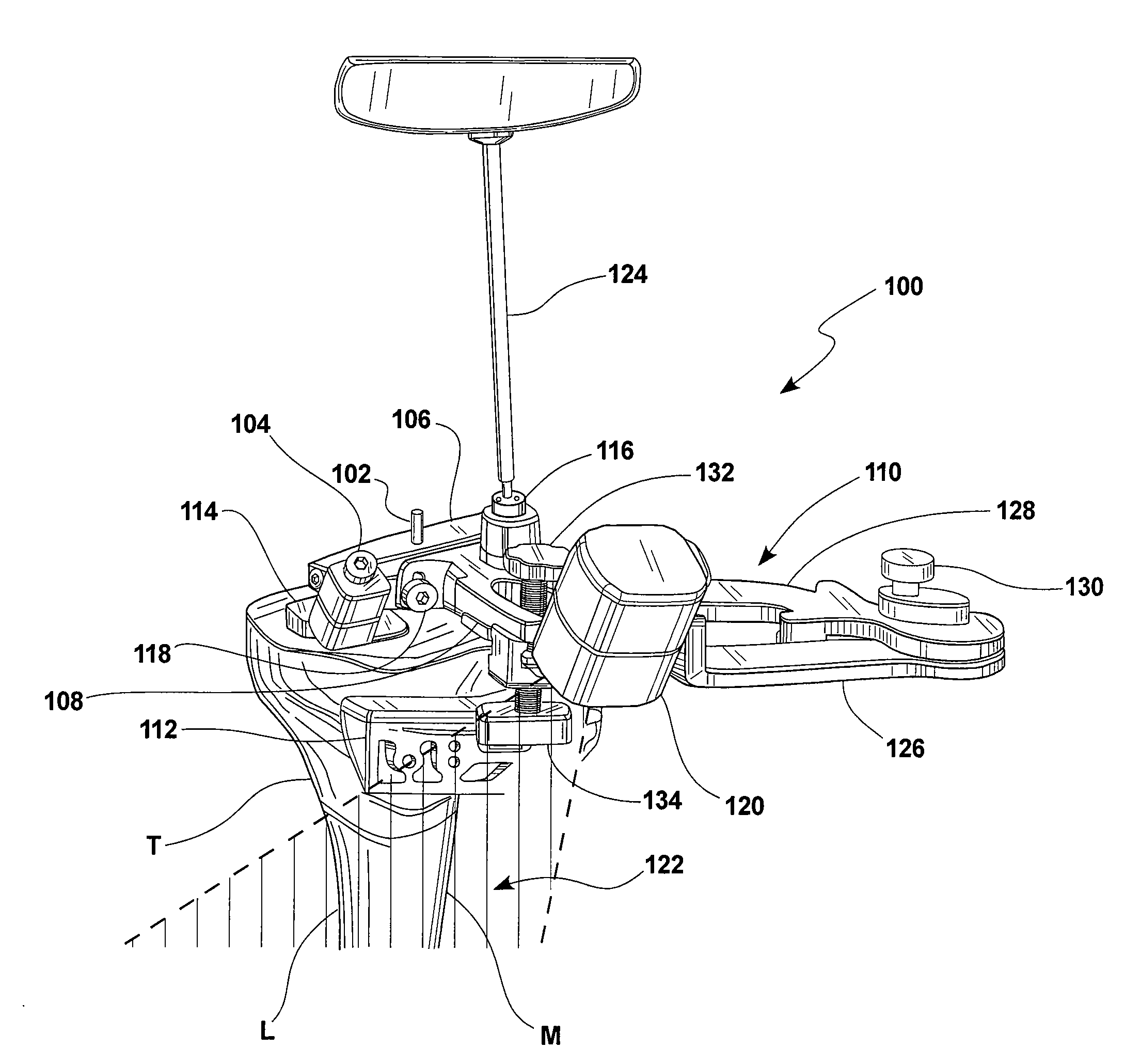
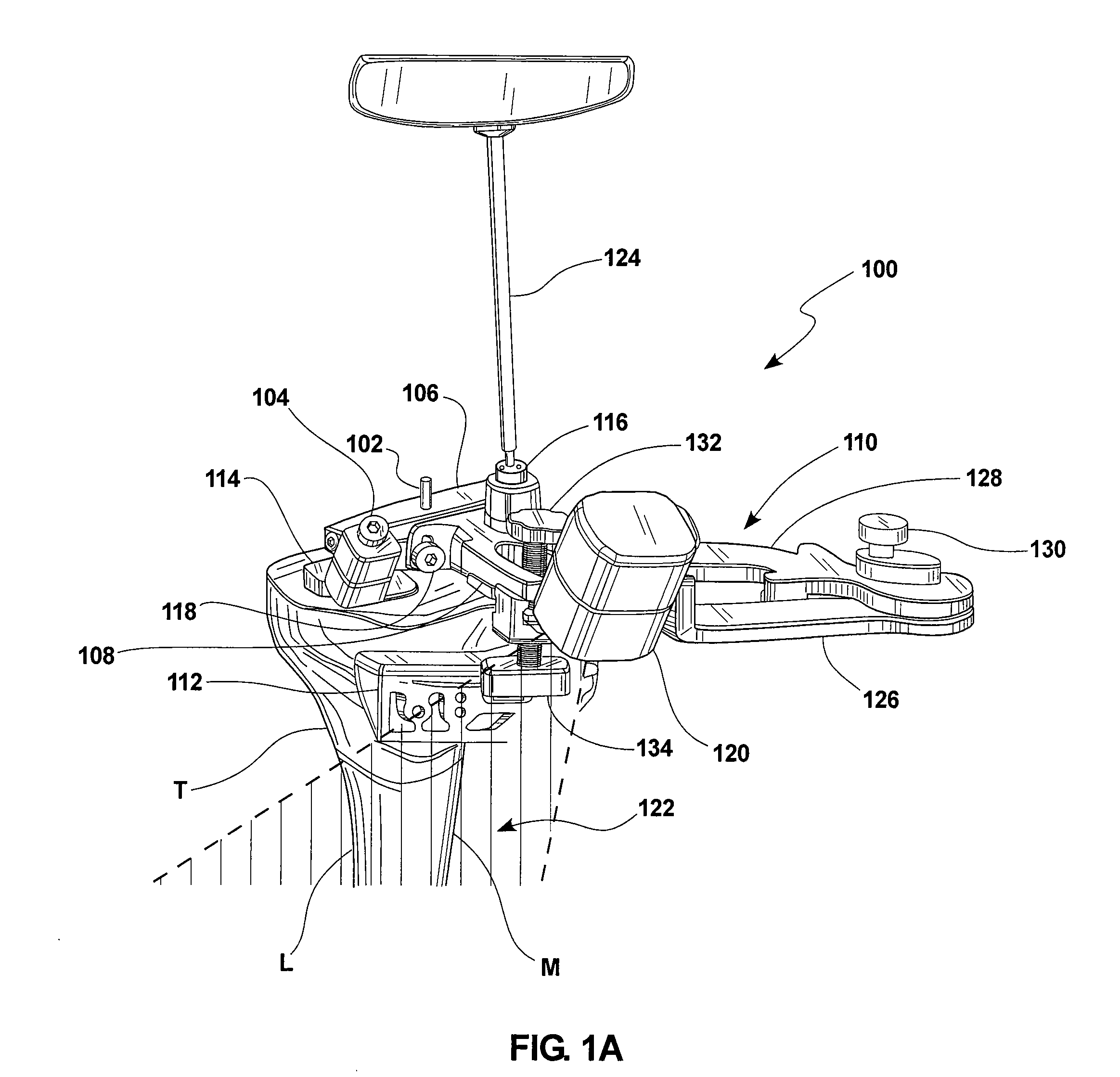
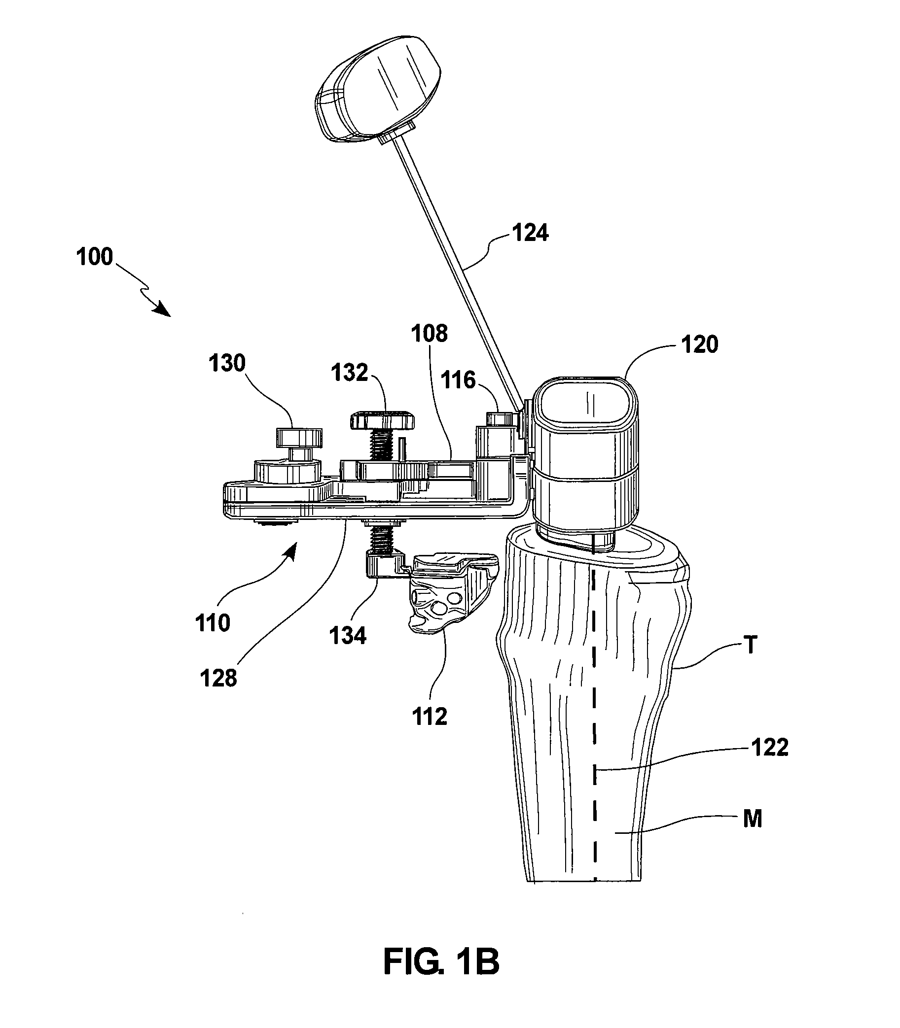
[0052]Referring to FIG. 1A, one embodiment of a bone cut positioning system 100 is shown attached to a tibia T. In this view, the tibia T is of a right leg and is in an anterior (front) facing orientation, with the lateral side L of the tibia T toward the left side of the figure and the medial side M of the tibia toward the right side of the figur...


PUM


Abstract

A method for positioning a bone cut on a bone may involve: coupling a bone cut positioning apparatus with a body bone; adjusting the positioning apparatus in a varus / valgus orientation relative to the body bone; adjusting the positioning apparatus in an anterior / posterior orientation relative to the body bone; and adjusting the positioning apparatus up or down to select a bone resection level.

Description

CROSS REFERENCE TO RELATED APPLICATION[0001]The present application is a continuation in part of U.S. patent application Ser. No. 12 / 616,747 filed Nov. 11, 2009 which is a continuation of PCT / US2009 / 063015 filed on Nov. 2, 2009, the full disclosures of which are incorporated herein by reference.BACKGROUND[0002]Embodiments of the here described relate to medical / surgical devices, systems and methods. More specifically, embodiments here described relate to devices, systems and methods for enhancing a knee surgery procedure.[0003]Approximately 550,000 total knee replacement surgeries (also referred to as total knee arthroplasty (“TKA”) are performed annually in the U.S. for the treatment of chronic knee pain and dysfunction. As the U.S. and world populations become older and more obese, knee replacement surgery will become even more common, as knee joints endure greater and greater wear and tear from their increased loads and years of stress. Conventional TKA surgery is often very effe...

Claims


Application Information

Patent Timeline
IPC IPC(8): A61B17/56
CPCA61B17/157A61B19/201A61B2019/4836A61B2019/462A61B2019/202A61B90/13A61B90/11A61B2090/062A61B2090/0807
Inventor FISHER, MICHAEL G.HEDLEY, ANTHONY K.NEVINS, RUSSELL T.JOHANNABER, KENNETH D.
Owner SYNVASIVE TECH
Learn More