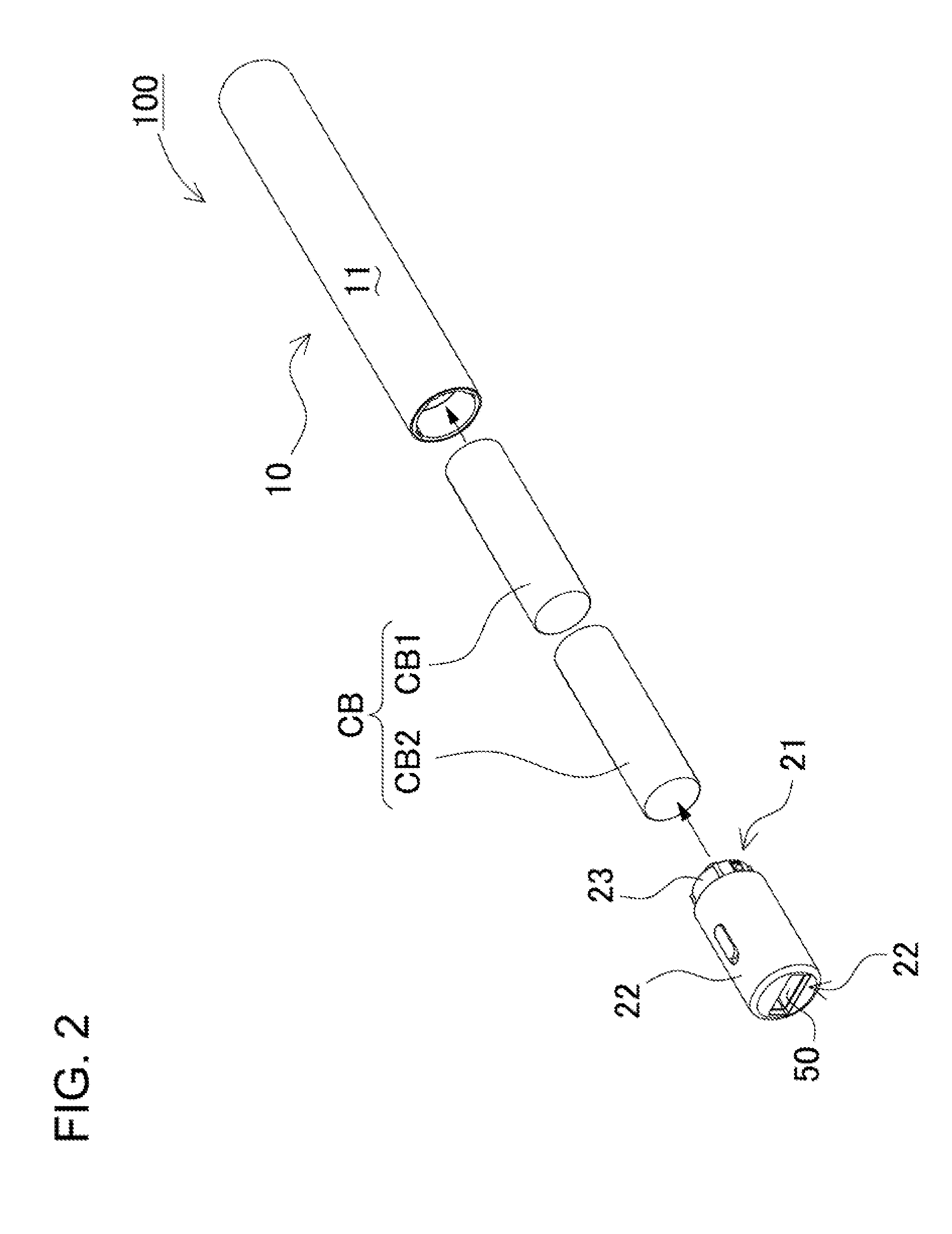
[0009]To achieve the object described above, a portable power source apparatus capable of holding circular cylindrical batteries for the first aspect of the present invention can be provided with a circular cylindrical main case 10 open at one end, having a bottom, made with an outside
diameter only slightly larger than a circular cylindrical battery CB, and capable of holding a plurality of circular cylindrical batteries CB that extend lengthwise, are stacked in the lengthwise direction, and are connected in series; an approximately circular cylindrical cap section 20 that closes-off the open end of the main case 10 in a removable manner, and is provided with a closing surface 21 facing the open end of the main case 10 and an exposed surface 22 externally exposed at the opposite end of the cap section 20 from the closing surface 21; a planar circuit board 38 housed in the cap section 20 with
voltage conversion circuitry mounted on-board to convert the voltage of the circular cylindrical batteries CB contained in the main case 10; and a power supply terminal 50 disposed in the exposed surface 22 of the cap section 20 and capable of outputting power from the circular cylindrical batteries CB contained in the main case 10. The circuit board 38 can be disposed across the inside
diameter of a circular cross-section of the cap section 20, and a pair of ribs 42 can be provided approximately perpendicular to the circuit board 38. With this structure, the outside
diameter of the cap section 20 can be restrained to approximately the same size as the circular cylindrical batteries while housing a relatively large circuit board disposed across the diameter of the cap section. Further, by disposing a pair of ribs perpendicular to the circuit board to support the circuit board from the backside, the ability to withstand
impact forces can be improved.
[0010]A portable power source apparatus capable of holding circular cylindrical batteries for the second aspect of the present invention can be provided with a circuit board holder 40 inside the cap section 20 to retain the circuit board 38 in a set disposition. The circuit board holder 40 can have a box-shape that extends in a direction approximately perpendicular to the plane of the circuit board 38 and can be provided with the pair of ribs 42 mentioned previously. With this structure, the circuit board and supporting circuit board holder are disposed in a perpendicular arrangement inside the cap section. As a result, cap section robustness can be improved while efficiently utilizing the space inside the cap section.
[0011]A portable power source apparatus capable of holding circular cylindrical batteries for the third aspect of the present invention can be provided with a conducting lead-plate 30 that contacts the circular cylindrical battery CB
electrode furthest away from the cap section 20 to electrically connect that
electrode to the circuit board 38. The main case 10 can be divided into an upper case 13 and a lower case 14, the upper case 13 and the lower case 14 can be formed from insulating material, and the lead-plate 30 can be disposed at the junction of the upper case 13 and the lower case 14 in an orientation perpendicular to the interface plane of the junction. With this structure, since the lead-plate that establishes
electrical connection of the circular cylindrical batteries also functions as a perpendicular support rib at the junction between the upper case and the lower case, the lead-plate can contribute to improving the strength of the junction. Further, since there is no need to allot space to run the lead-plate inside the main case, this configuration can serve to reduce the size of the portable power source apparatus.
[0012]A portable power source apparatus capable of holding circular cylindrical batteries for the fourth aspect of the present invention can have a main case 10 provided with an outer case 11 that covers the outside of an inner case 12 made up of the upper case 13 and the lower case 14, and the outer case 11 can be made of
metal. With this structure, the inner surface of the main case can be insulating to prevent malfunctions such as circular cylindrical battery short circuits while improving strength and long-term durability with a
metal exterior.
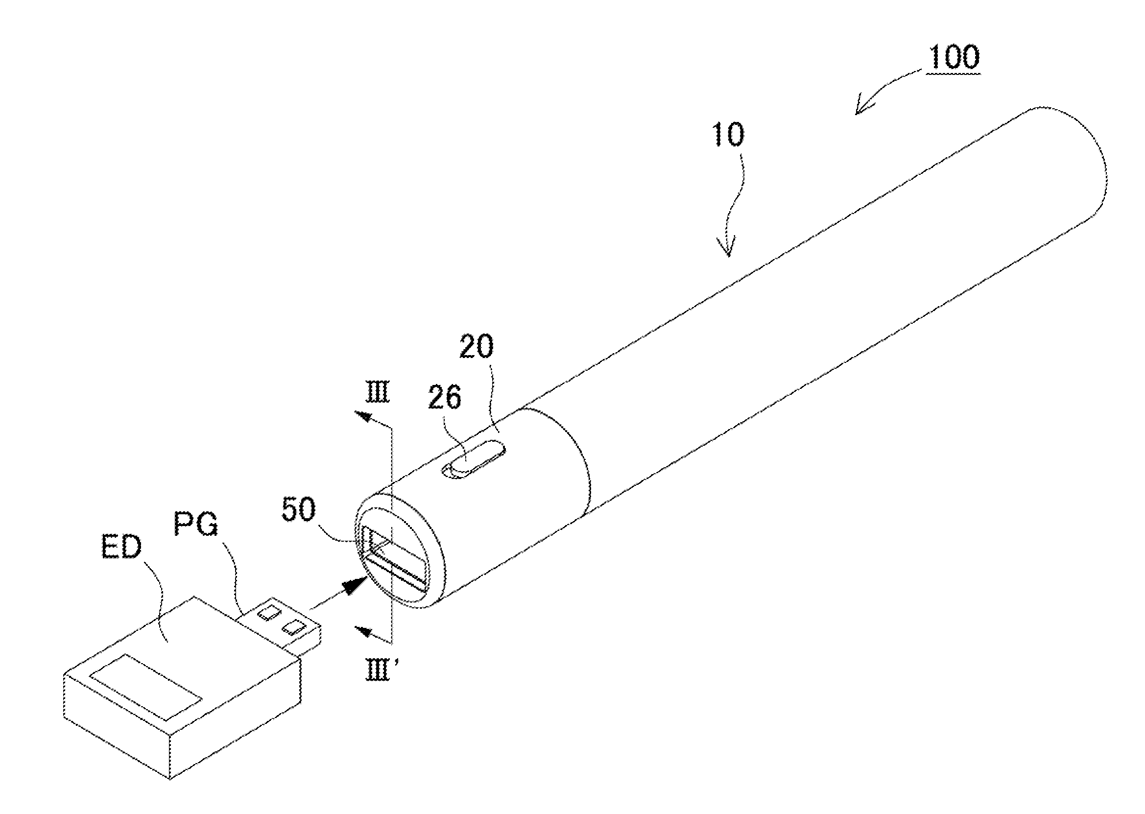
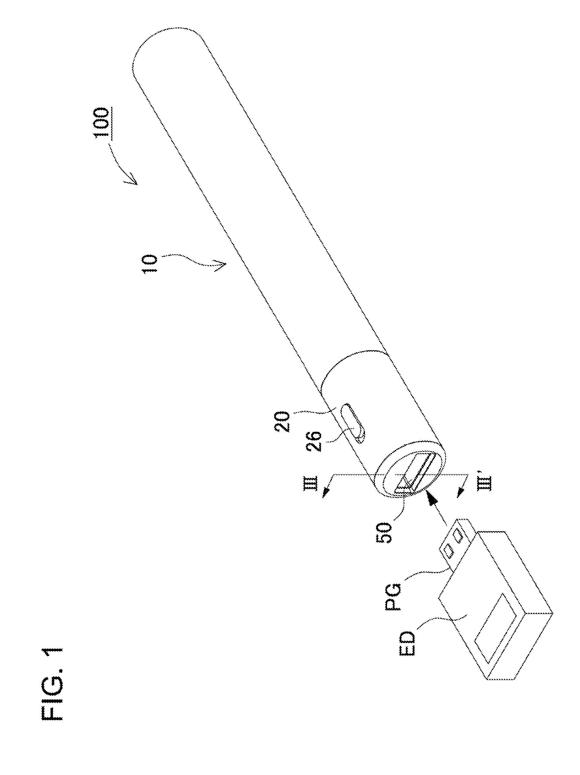
[0015]A portable power source apparatus capable of holding circular cylindrical batteries for the seventh aspect of the present invention can have the power supply terminal 50 in a rectangular opening along a diameter of the exposed region of the cap section 20. Consequently, when an
electronic equipment plug is inserted in the power supply terminal of the portable power source apparatus to connect those devices, the circular cylindrical portable power source apparatus is prevented from rolling along a supporting surface, and the connected unit can be stably placed even on a slightly inclined surface.
[0017]A portable power source apparatus capable of holding circular cylindrical batteries for the ninth aspect of the present invention can be provided with a power switch 26 on the lateral surface of the circular cylindrical cap section 20. The power switch 26 can operate to begin supplying power from the power supply terminal 50 at a voltage converted from the circular cylindrical battery CB voltage by the voltage conversion circuitry. As a result, the supply of power can be initiated at the desired time, and
power consumption waste can be avoided.
