
Card reader

a card reader and card reader technology, applied in the direction of coupling device connection, electrical apparatus casing/cabinet/drawer, instruments, etc., can solve the problem of really unacceptable cost, achieve high expandability, reduce time and labor, and really unacceptable cost

Inactive Publication Date: 2011-05-05
HEISEI ELECTRONICS CO LTD
View PDF18 Cites 0 Cited by
  • Summary
  • Abstract
  • Description
  • Claims
  • Application Information

AI Technical Summary

Benefits of technology

[0009]The primary object of the present invention is to provide a card reader which is composed of a housing accommodating interface units, with the interface units being storage devices such as MS (Memory Stick), CF (Compact Flash), SD (Secure Digital), XD (Extreme Digital), USB, microSD (micro Secure Digital) or M2 (Memory Stick Micro). These interface units operate independently and are connected to a control unit respectively. The interface units can be dismantled independently according to a user's preferences, to carry out replacement, updating or repairing, such that when the user is to repair or update, he or she only needs to dismantle the interface unit to be repaired or updated. By the aforementioned technologies, the issues existing in the conventional built-in card reader that although the built-in card reader can be inserted with plural memory cards of various interfaces, if one slot is damaged or malfunctioning, then the entire card reader has to be dismantled, which is very troublesome; and moreover, the damaged slot cannot be simply dismantled for repairing and in terms of expandability, the connectors cannot be replaced according to various technologies and as the entire card reader needs to be replaced, the cost spent is really unacceptable; can be solved. Therefore, by the plural interface units which are provided independently, the user can dismantle the individual interface unit to be replaced, updated or repaired, not like that when the conventional built-in card reader is to be replaced, updated or repaired, the entire card reader needs to be dismantled. Accordingly, the card reader of the present invention is provided with extremely high expandability to reduce time and labor works and save an unnecessary cost spent. In addition, as the independent slots are used, the user can be more clearly and explicitly aware of positions of all kinds of memory slots and will not insert by a mistake to damage the card reader or the memory card.

Problems solved by technology

By the aforementioned technologies, the issues existing in the conventional built-in card reader that although the built-in card reader can be inserted with plural memory cards of various interfaces, if one slot is damaged or malfunctioning, then the entire card reader has to be dismantled, which is very troublesome; and moreover, the damaged slot cannot be simply dismantled for repairing and in terms of expandability, the connectors cannot be replaced according to various technologies and as the entire card reader needs to be replaced, the cost spent is really unacceptable; can be solved.

Method used


Image

  • Card reader
  • Card reader
  • Card reader

Examples


Embodiment Construction

[0015]Referring to FIG. 2 and FIG. 3, it shows a three-dimensional schematic view and a block diagram, of a preferred embodiment of the present invention. As shown in the drawing, a card reader 10 of the present invention comprises:

[0016]a housing 11, which is further provided with a cover board 111 being disposed with perforations 112 at locations corresponding to interface units 12 described below, and an interior of which is further defined with holding slots 113;

[0017]the plural built-in interface units 12 which are accommodated in the holding slots 113 of the housing 11 independently, and are connected respectively with a control unit 13 that can be a single chip, with the interface units 12 being storage devices, such as MS, CF, SD, XD, USB, microSD or M2; and

[0018]plural connection units 14 which are assembled correspondingly with the aforementioned control units 13 and can be further connected with a main control device 15 that can be a photo developing device, a printer, a ...


PUM


Abstract

A card reader includes a housing, an interior of which is defined with plural holding slots accommodating interface units respectively. The interface units are connected respectively with control units which are primarily a single chip. The interface units are storage devices, such as MS, CF, SD, XD, USB, microSD or M2. The housing is further provided with a cover board on which are disposed with perforations at locations corresponding to the interface units. When a user is to replace, update or repair the card reader, he or she can take down the cover board and then perform a respective operation to the interface unit to be replaced, updated or repaired independently, without removing other interface units together. Therefore, time and labor works can be reduced, expandability is high, and an unnecessary cost spent can be saved.

Description

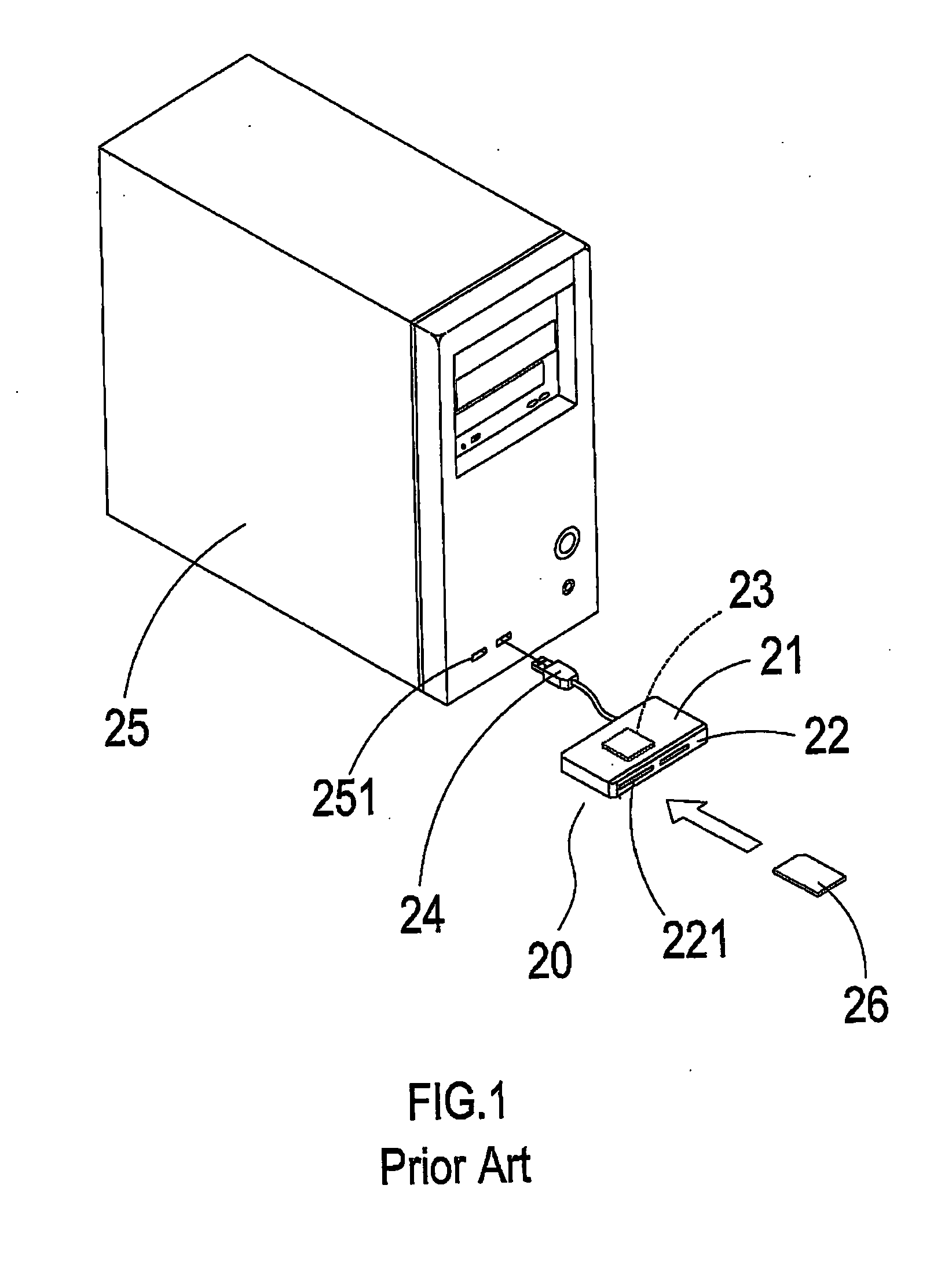
BACKGROUND OF THE INVENTION[0001]a) Field of the Invention[0002]The present invention relates to a card reader, and more particularly to a card reader which can be repaired, replaced and updated independently.[0003]b) Description of the Prior Art[0004]Referring to FIG. 1, it shows a three-dimensional schematic view of a conventional card reader. The card reader 20 is provided with a housing 21, a panel 22 which is located at an end surface of the housing 21 and is equipped with plural slots 221 (multi-in-one slot), a processing unit 23 which is located in the housing 21 and a connection part 24 which is connected with the processing unit 23 and is extended out of the other end surface of the housing 21. Accordingly, the connection part 24 can be connected externally to a connection port 251 of a computer 25 and a required memory card 26 can be inserted into the slot 221, thereby facilitating the computer 25 to read from and write into the memory card 26.[0005]Although the aforementi...

Claims


Application Information

Patent Timeline
Patent Type & Authority Applications(United States)
IPC IPC(8): G06F1/16
CPCG06F1/1607G06K7/0043G06K7/0034G06K7/0013
Inventor PANG, YU-CHING
Owner HEISEI ELECTRONICS CO LTD
Learn More