
Apparatus and Method for Calculating Bandwidth Extension Data Using a Spectral Tilt Controlled Framing

a bandwidth extension and spectral tilt control technology, applied in the field of audio coding/decoding, bandwidth extension, can solve the problems of reducing the quality of estimated signals, particularly demanding speech signals, and difficult situations, and achieve the effect of higher length of bandwidth extension parameter frames

Active Publication Date: 2011-04-28
FRAUNHOFER GESELLSCHAFT ZUR FOERDERUNG DER ANGEWANDTEN FORSCHUNG EV
View PDF4 Cites 79 Cited by
  • Summary
  • Abstract
  • Description
  • Claims
  • Application Information

AI Technical Summary

Benefits of technology

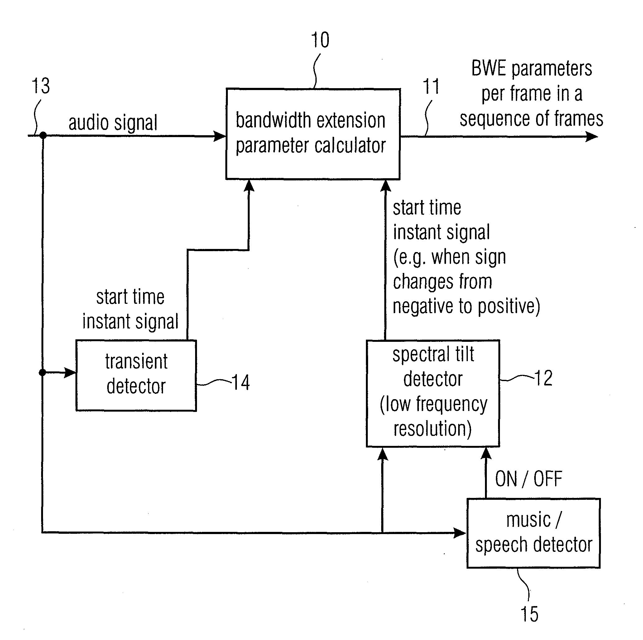
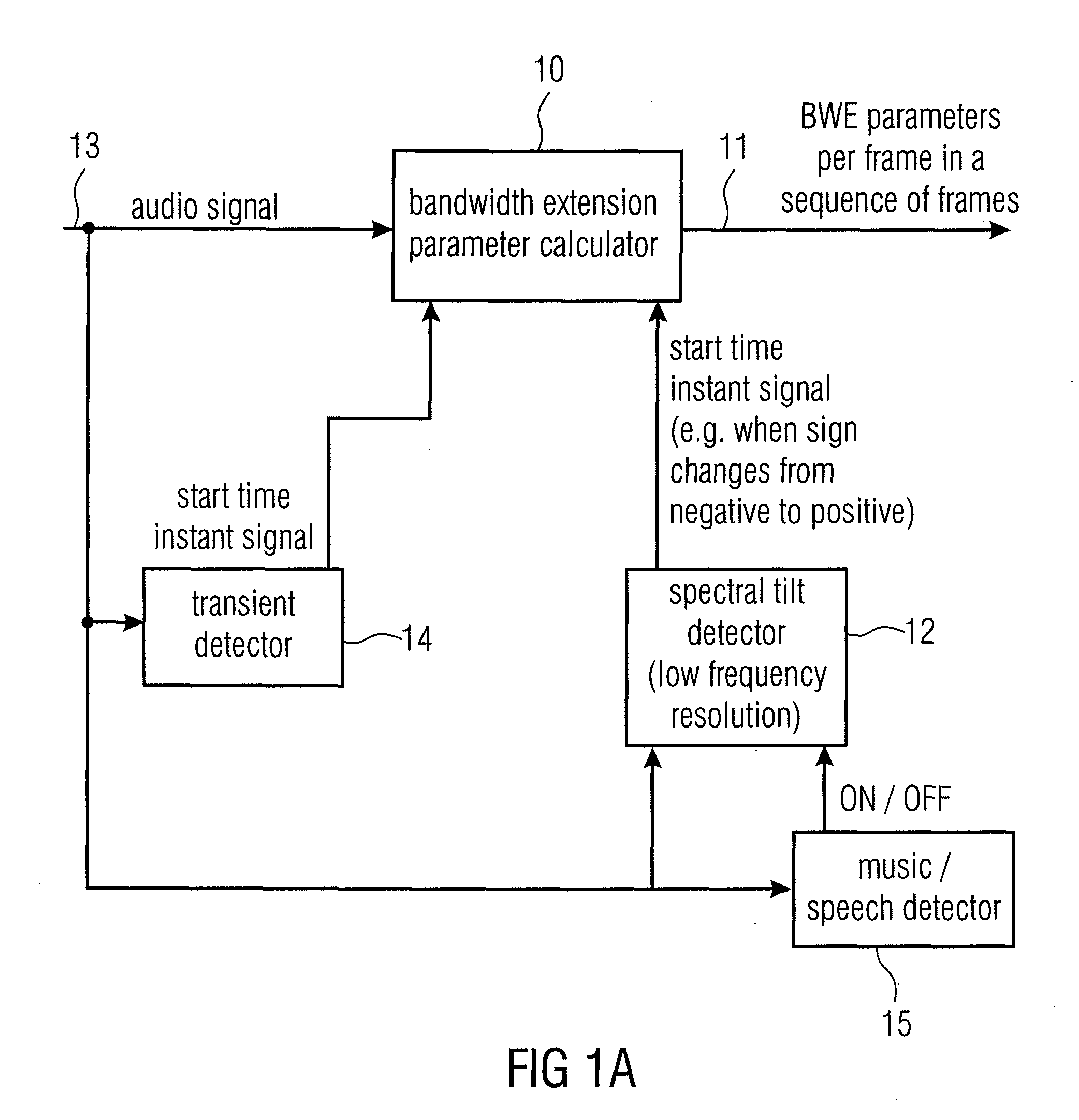
[0018]Advantageously, the spectral tilt detector cooperates with a transient detector, which is adapted for detecting an energy change, i.e., an energy increase or decrease of the whole audio signal. In an embodiment, the length of a bandwidth extension parameter frame is higher, when a transient in the signal has been detected, while the controllable bandwidth extension parameter calculator sets a shorter length of a frame, when the spectral tilt detector has signaled a start time instant signal.

Problems solved by technology

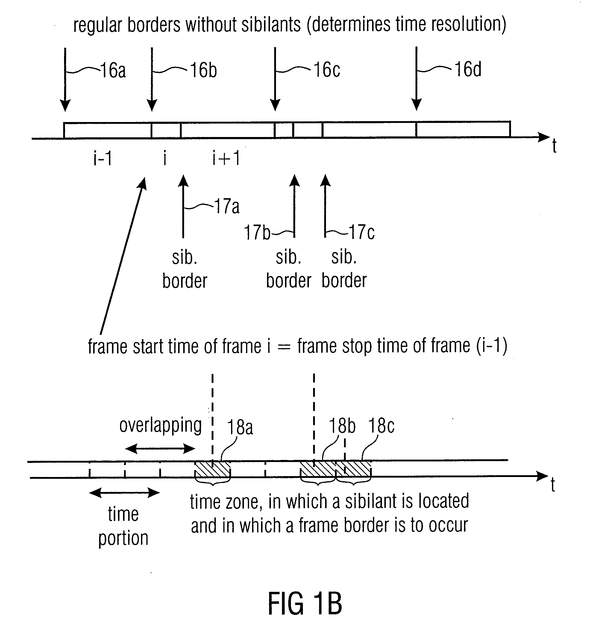
The coding of speech signals is particularly demanding due to the fact that speech comprises not only vowels, which have a predominantly harmonic content, in which the majority of the overall energy is concentrated in the lower part of the spectrum, but also contains a significant amount of sibilants.
The situation, however, becomes problematic, when sibilants occur in the context of bandwidth extension.
However, a transient detector looking for an increase (or decrease) in energy will not detect this energy shift, so that spectral envelope data for a spectral envelope frame, which covers a time portion before or after the sibilant, will be affected by the energy shift within the spectrum.
This will result in a decrease of quality of the estimated signal.

Method used


Image

  • Apparatus and Method for Calculating Bandwidth Extension Data Using a Spectral Tilt Controlled Framing
  • Apparatus and Method for Calculating Bandwidth Extension Data Using a Spectral Tilt Controlled Framing
  • Apparatus and Method for Calculating Bandwidth Extension Data Using a Spectral Tilt Controlled Framing

Examples


Embodiment Construction

[0028]Before discussing FIGS. 1 and 2 in detail, a bandwidth extension scenario is described with respect to FIGS. 3 and 4.

[0029]FIG. 3 shows an embodiment for the encoder 300, which comprises SBR related modules 310, an analysis QMF bank 320, a low pass filter (LP-filter) 330, an AAC core encoder 340 and a bit stream payload formatter 350. In addition, the encoder 300 comprises the envelope data calculator 210. The encoder 300 comprises an input for PCM samples (audio signal 105; PCM=pulse code modulation), which is connected to the analysis QMF bank 320, and to the SBR-related modules 310 and to the LP-filter 330. The analysis QMF bank 320 may comprise a high pass filter to separate the second frequency band 105b and is connected to the envelope data calculator 210, which, in turn, is connected to the bit stream payload formatter 350. The LP-filter 330 may comprise a low pass filter to separate the first frequency band 105a and is connected to the AAC core encoder 340, which, in t...


PUM


Abstract

An apparatus for calculating bandwidth extension data of an audio signal in a bandwidth extension system, in which a first spectral band is encoded with a first number of bits and a second spectral band different from the first spectral band is encoded with a second number of bits, the second number of bits being smaller than the first number of bits, has a controllable bandwidth extension parameter calculator for calculating bandwidth extension parameters for the second frequency band in a frame-wise manner for a sequence of frames of the audio signal. Each frame has a controllable start time instant. The apparatus additionally includes a spectral tilt detector for detecting a spectral tilt in a time portion of the audio signal and for signaling the start time instant for the individual frames of the audio signal depending on spectral tilt.

Description

CROSS-REFERENCE TO RELATED APPLICATION[0001]This application is a U.S. National Phase entry of PCT / EP2009 / 004520 filed Jun. 23, 2009, and claims priority to U.S. Patent Application No. 61 / 079,871 filed Jul. 11, 2008, each of which is incorporated herein by references hereto.BACKGROUND OF THE INVENTION[0002]The present invention is related to audio coding / decoding and, particularly, to audio coding / decoding in the context of bandwidth extension (BWE). A well known implementation of BWE is spectral bandwidth replication (SBR), which has been standardized within MPEG (Moving Picture Expert Group).[0003]WO 00 / 45378 discloses an efficient spectral envelope coding using variable time / frequency resolution and time / frequency switching. An analogue input signal is fed to an A / D converter, forming a digital signal. The digital audio signal is fed to a perceptual audio encoder, where source coding is performed. In addition, the digital signal is fed to a transient detector and to an analysis f...

Claims


Application Information

Patent Timeline
IPC IPC(8): G10L19/00G10L25/93
CPCG10L21/038G10L19/022
Inventor NEUENDORF, MAXKRAEMER, ULRICHNAGEL, FREDERIKDISCH, SASCHAWABNIK, STEFAN
Owner FRAUNHOFER GESELLSCHAFT ZUR FOERDERUNG DER ANGEWANDTEN FORSCHUNG EV
Learn More