High voltage (HV) impedance device with surface leakage proof configuration applied in hv divider

a technology of leakage proof configuration and high voltage, applied in resistor details, resistors, electrical devices, etc., can solve the problems of criticized and conventional hv dividers that are long enough for linear output voltages, and achieve the effect of reducing the length of a high impedance unit and increasing the resistance of external environmen

Active Publication Date: 2017-11-16
ELMATEK INTION CORP
View PDF5 Cites 0 Cited by
  • Summary
  • Abstract
  • Description
  • Claims
  • Application Information

AI Technical Summary

Benefits of technology

The present patent offers a HV impedance device with a surface leakage-proof configuration for use in a HV divider. The device has a high impedance unit, an inner case, and an outer case, with interlayers between them containing inert gas and being sealed for isolation. This prevents leakage current and maintains the linearity of output voltages based on the voltage division rule. Additionally, the device is designed to allow for convenient movement and applications, reducing the height of the device in an identical high-voltage condition.

Problems solved by technology

Thus, a conventional HV divider is long enough for linearity of output voltages but criticized because of some drawbacks such as movement inconvenient and collapse.

Method used


Image

  • High voltage (HV) impedance device with surface leakage proof configuration applied in hv divider
  • High voltage (HV) impedance device with surface leakage proof configuration applied in hv divider
  • High voltage (HV) impedance device with surface leakage proof configuration applied in hv divider

Examples


Embodiment Construction

[0023]The following description is about embodiments of the present invention; however it is not intended to limit the scope of the present invention.

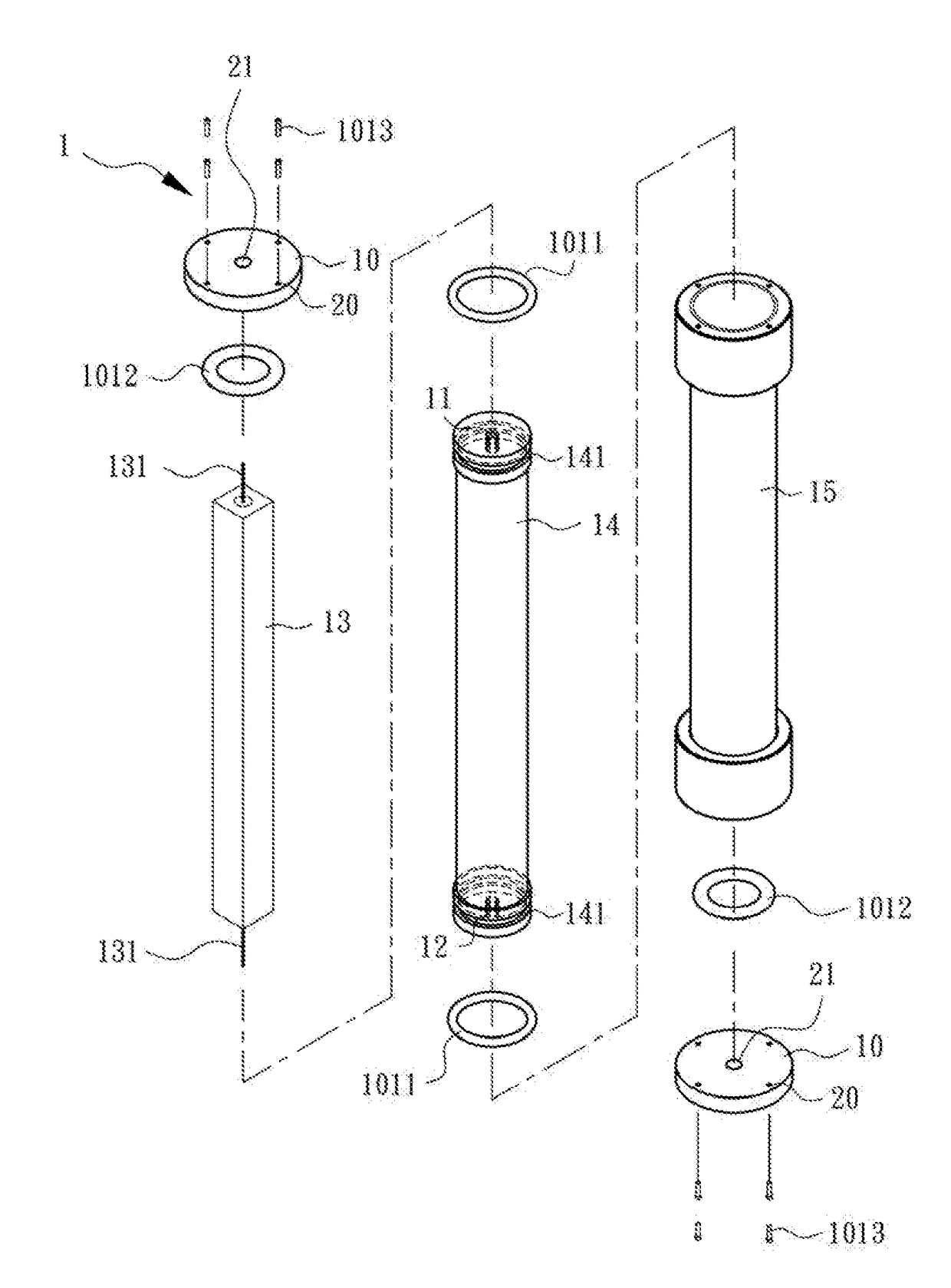
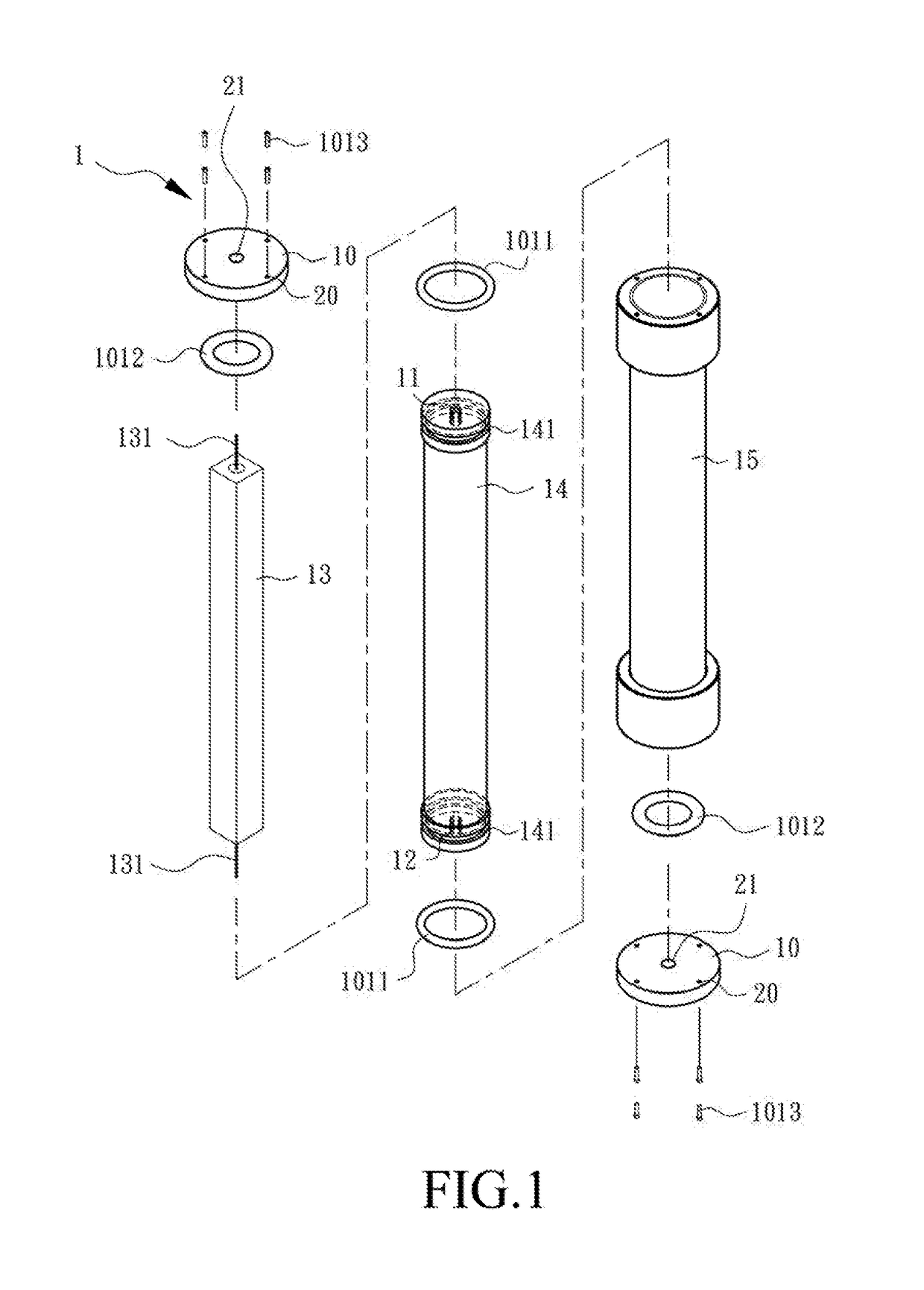
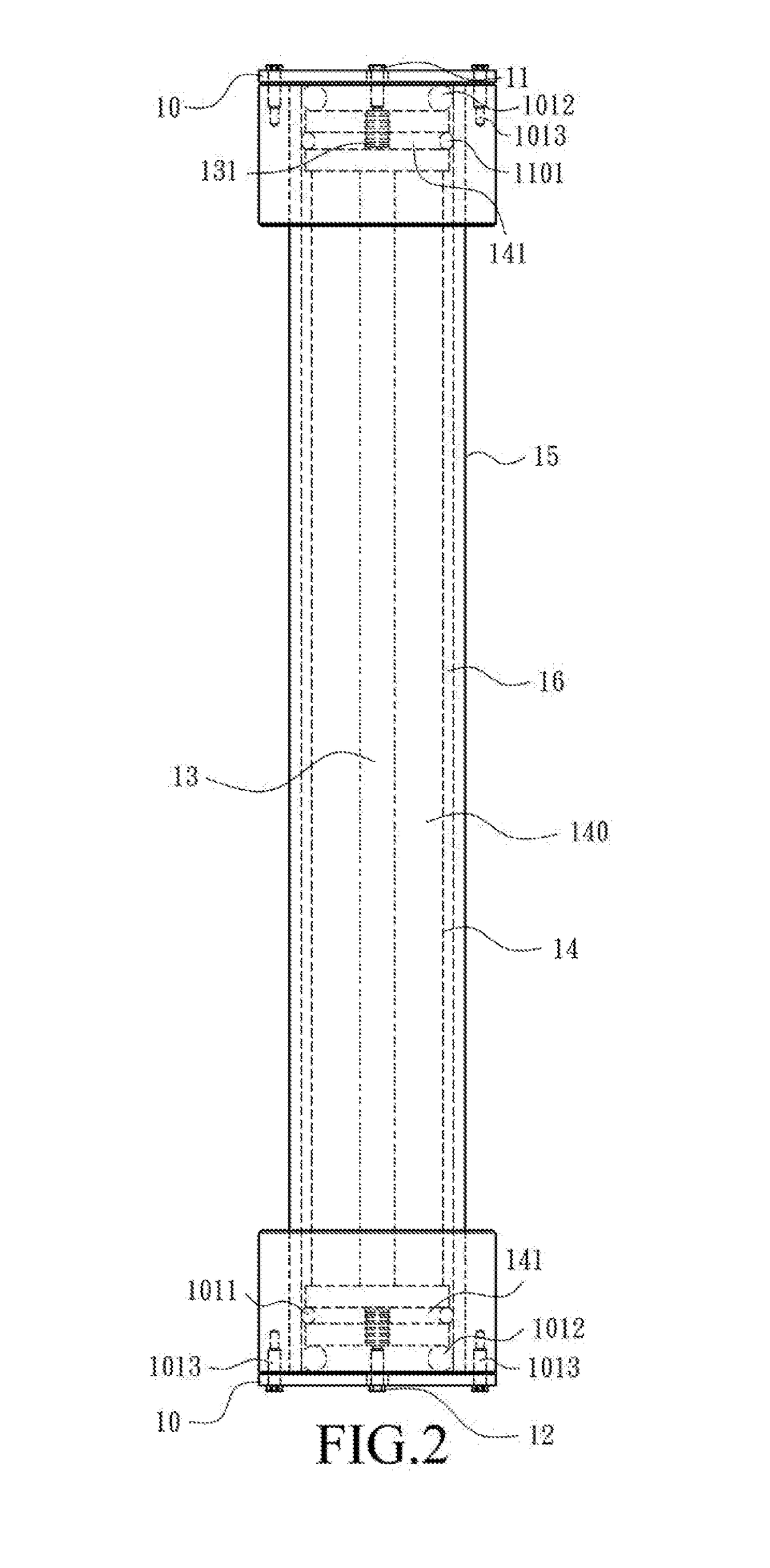
[0024]Refer to FIG. 1 which is an exploded schematic view illustrating a high voltage (HV) impedance device 1 with surface leakage proof configuration applied in a HV divider in an embodiment. The HV impedance device 1 is provided with an inner case 14 and an outer case 15, both of which are insulators, between a first end 11 and a second end 12: the inner case 14 is a hollow tube (for example, a cylindrical tube) with an inner space 140 in which a high impedance unit 13 is installed and an insulating material 140 or inert gas is filled (FIG. 2); the outer case 15, which is a hollow tube (for example, a cylindrical tube) with outer diameters at both ends greater than outer diameters of other tubes, is integrated with the inner case 14 for development of a gap taken as a closed interlayer 16 (FIG. 2) to prevent leakage current at end po...


PUM


Abstract

A high voltage impedance device with surface leakage proof configuration is applied in a divider. Aforementioned divider is assembled by a high impedance element, an inner case body and an outer case body. The high impedance element is sealed in the inner case body and a closed interlayer between the inner case body and the outer case body is filled with noble gas as an insulating layer. While the high impedance element is applied in high voltage, the closed interlayer can prevent the current-leakage from forming impedance paralleled with the high impedance element. The current-leakage is formed on the surface of insulting portion, or is formed by moisture, dust or corona effect. Therefore, the current-leakage proof divider may maintain the stability / linearity of the voltage division and then reduce the distance between two ends of the high impedance element effectively and still maintain the linearity of measuring voltage.

Description

BACKGROUND OF THE INVENTION1. Field of the invention[0001]The present disclosure relates to a high voltage (HV) impedance device, particularly a HV impedance device with surface leakage proof configuration applied in a HV divider.2. Description of the prior art[0002]For high voltage equipment, the output voltages based on the voltage division rule are derived from a high-voltage (HV) impedance device in which there are several high impedance units installed in series for measuring high voltage and calculating required voltage values. However, leakage current will be detected at a high impedance unit installed in a humid or dusty environment when voltage applied at both ends of the high impedance unit is increased gradually and up to a certain level. Moreover, a parallel circuit induced by both the leakage current and the high impedance unit has a negative effect on measured voltage which may be deviated from linearity with higher voltage applied. Therefore, a HV impedance device res...

Claims


Application Information

Patent Timeline
Patent Type & Authority Applications(United States)
IPC IPC(8): H01C1/026H01C13/00
CPCH01C1/026H01C13/00H01C13/02
Inventor TUNG, KUNG-CHAOTUNG, STEVEN PO-CHENG
Owner ELMATEK INTION CORP
Why Eureka
Try Eureka