
Methods for carrier frequency offset detection and compensation and transmitters and receivers utilizing the same

a carrier frequency offset and compensation technology, applied in the field of carrier frequency offset detection in orthogonal frequency division multiplexing (ofdm) systems, can solve the problems of increasing the performance and bit error rate of the ofdm system in a high speed environment, and the system is affected by doppler

Inactive Publication Date: 2011-04-28
NAT TAIWAN UNIV
View PDF4 Cites 26 Cited by
  • Summary
  • Abstract
  • Description
  • Claims
  • Application Information

AI Technical Summary

Benefits of technology

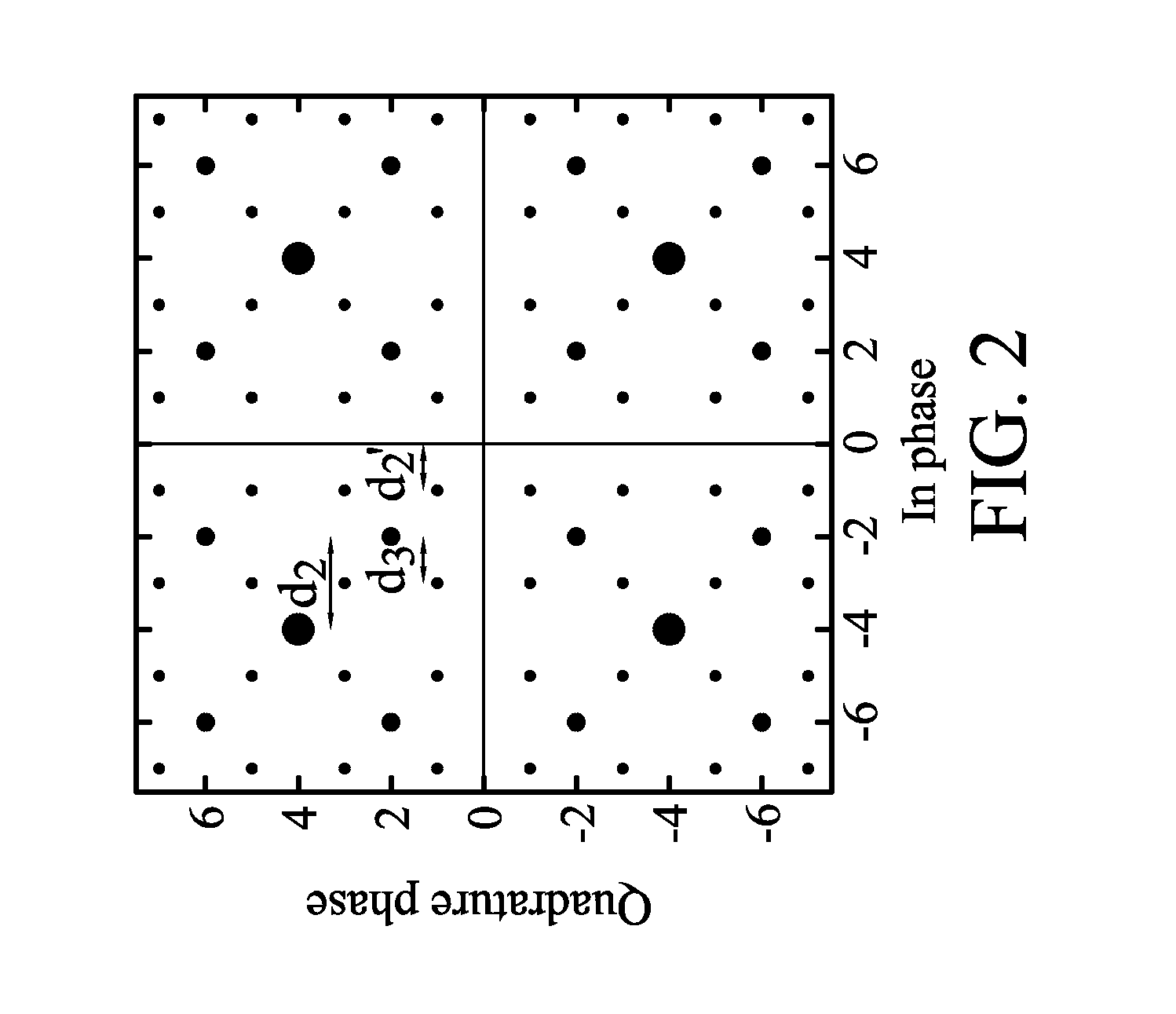
[0008]Transmitters, receivers, and methods for carrier frequency offset detection and compensation are provided. An exemplary embodiment of a transmitter comprises an encoding module, an adaptive hierarchical signal mapping module and a transceiver module. The encoding module receives an input signal and encodes the input signal. The input signal comprises data to be transmitted. The adaptive hierarchical signal mapping module modulates the encoded signal according to one or more hierarchical level distance ratios to obtain a plurality of modulated symbols. The hierarchical level distance ratios define distances between the modulated symbols. The transceiver module generates a radio frequency signal according to the modulated symbols and transmits the radio frequency signal to an air interface.

Problems solved by technology

However, the OFDM system is affected by Doppler effect under an environment of high speed movement, such as that which may be found with high speed rail trains.
Carrier frequency offset will destroy the orthogonality between subcarriers and generate inter-carrier interference (ICI) between the subcarriers such that performance and bit error rate of the OFDM system in a high speed environment decreases and increases, respectively.

Method used


Image

  • Methods for carrier frequency offset detection and compensation and transmitters and receivers utilizing the same
  • Methods for carrier frequency offset detection and compensation and transmitters and receivers utilizing the same
  • Methods for carrier frequency offset detection and compensation and transmitters and receivers utilizing the same

Examples


Embodiment Construction

[0032]The following description is of the best-contemplated mode of carrying out the invention. This description is made for the purpose of illustrating the general principles of the invention and should not be taken in a limiting sense. The scope of the invention is best determined by reference to the appended claims.

[0033]Transmitter Structure and Hierarchical Modulation

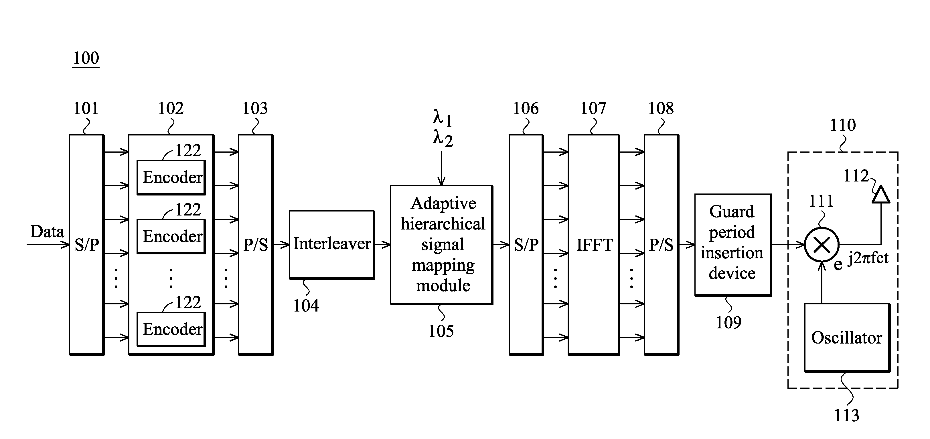
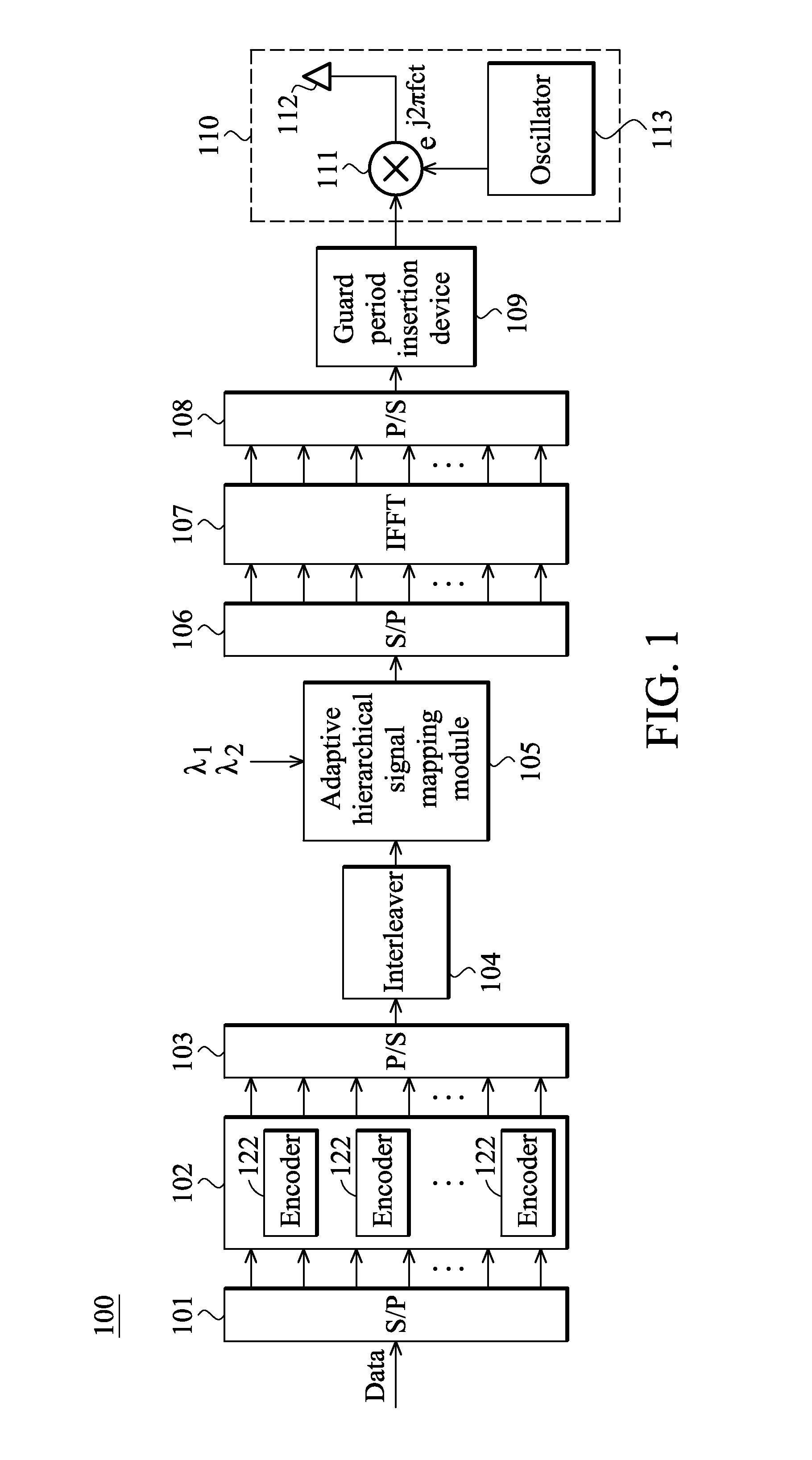
[0034]FIG. 1 shows a block diagram of a transmitter 100 according to an embodiment of the invention. In the embodiment of the invention, the transmitter 100 may be utilized in an Orthogonal Frequency Division Multiplexing (OFDM) communication system. As shown in FIG. 1, the transmitter 100 may comprise serial to parallel (S / P) converters 101 and 106, parallel to serial (P / S) converters 103 and 108, an encoding module 102, an interleaver 104, an adaptive hierarchical signal mapping module 105, an (Inverse Fast Fourier Transform (IFFT) module 107, and a guard period insertion device 109 and a transceiver module 110.

[...


PUM


Abstract

A transmitter includes an encoding module, an adaptive hierarchical signal mapping module and a transceiver module. The encoding module receives an input signal and encodes the input signal. The input signal includes data to be transmitted. The adaptive hierarchical signal mapping module modulates the encoded signal according to one or more hierarchical level distance ratios to obtain modulated symbols. The hierarchical level distance ratio defines distances between the modulated symbols. The transceiver module generates a radio frequency signal according to the modulated symbols and transmits the radio frequency signal to an air interface.

Description

[0001]This Application claims priority of Taiwan Patent Application No. 98135738, filed on Oct. 22, 2009, the entirety of which is incorporated by reference herein.BACKGROUND OF THE INVENTION[0002]1. Field of the Invention[0003]The invention relates to a method and apparatus for carrier frequency offset detection in an Orthogonal Frequency Division Multiplexing (OFDM) system, and more particularly, to a method and apparatus for using a hierarchically modulated data signal to detect carrier frequency offset.[0004]2. Description of the Related Art[0005]Recently, Orthogonal Frequency Division Multiplexing (OFDM) has become an important wireless communication technology. Because of the high transmission rate of OFDM technology offers high transmission rates, data can be easily and efficiently transmitted and received in a wireless communication environment. Therefore, OFDM technology has been widely applied to, for example, Digital Audio Broadcasting (DAB), Digital Video Broadcasting-Te...

Claims


Application Information

Patent Timeline
Patent Type & Authority Applications(United States)
IPC IPC(8): H04B1/38H04L27/36H04K1/10
CPCH04L27/2604H04L27/3488H04L27/2659
Inventor WU, JING-SHOWNTSAO, HEN-WAILEE, YANG-HANSHIAO, YU-LIN
Owner NAT TAIWAN UNIV
Learn More