
High-Speed Electromagnetic Nail Gun

a nail gun and electromagnetic technology, applied in the field of high-speed electromagnetic nail guns, can solve the problems of high cost, high cost, high cost and inconvenience, and achieve the effects of low manufacturing cost, less vibration and noise, and simple structur

Inactive Publication Date: 2011-04-28
BEIJING DAFENG TECH
View PDF10 Cites 8 Cited by
  • Summary
  • Abstract
  • Description
  • Claims
  • Application Information

AI Technical Summary

Benefits of technology

[0005]The objective of the present invention is to furnish a high-speed electromagnetic nail gun with a lever, which uses electromagnetism as the driving force and drives the firing spin, with variable speeds, through the lever to launch nails. The present invention has the following advantages: simple structure, lightweight, low manufacture cost, little vibration and noise when used, convenient operation, without air compressor accessories, and excellent performance.
[0008]The present invention utilizes directly electromagnetic as the driving force, drives the firing pin by virtue of a lever to launch nails with variable speeds. As a result, the nail gun of the present invention is simple structure, lightweight, low manufacture cost, less vibration and noise, convenient operation, without any air compressor accessories, easy to carry it around. Compared to the pneumatic nail gun, when the launching effect is the same, the present invention has faster launching speed, and the manufacture cost is decreased by 60%.

Problems solved by technology

However, these type of pneumatic nail guns have the disadvantages of being complicated, heavy, expensive to manufacture, high cost, vibrating when used, noisy and etc. not only, but also needs to be equipped with a compressor, a pressure adjustment and gas control device, and pipes and connector assembly that are used for connecting the nail gun and the compressor; therefore, it leads to high cost and inconvenience; moreover, when operating the nail gun, the users have to carry those pipes around.
Besides, because the nail gun converts electrical energy into the potential energy of the compressed air and then converts the potential energy of the compressed air into kinetic energy, the double energy conversions bring low energy efficiency.

Method used


Image

  • High-Speed Electromagnetic Nail Gun
  • High-Speed Electromagnetic Nail Gun
  • High-Speed Electromagnetic Nail Gun

Examples


Embodiment Construction

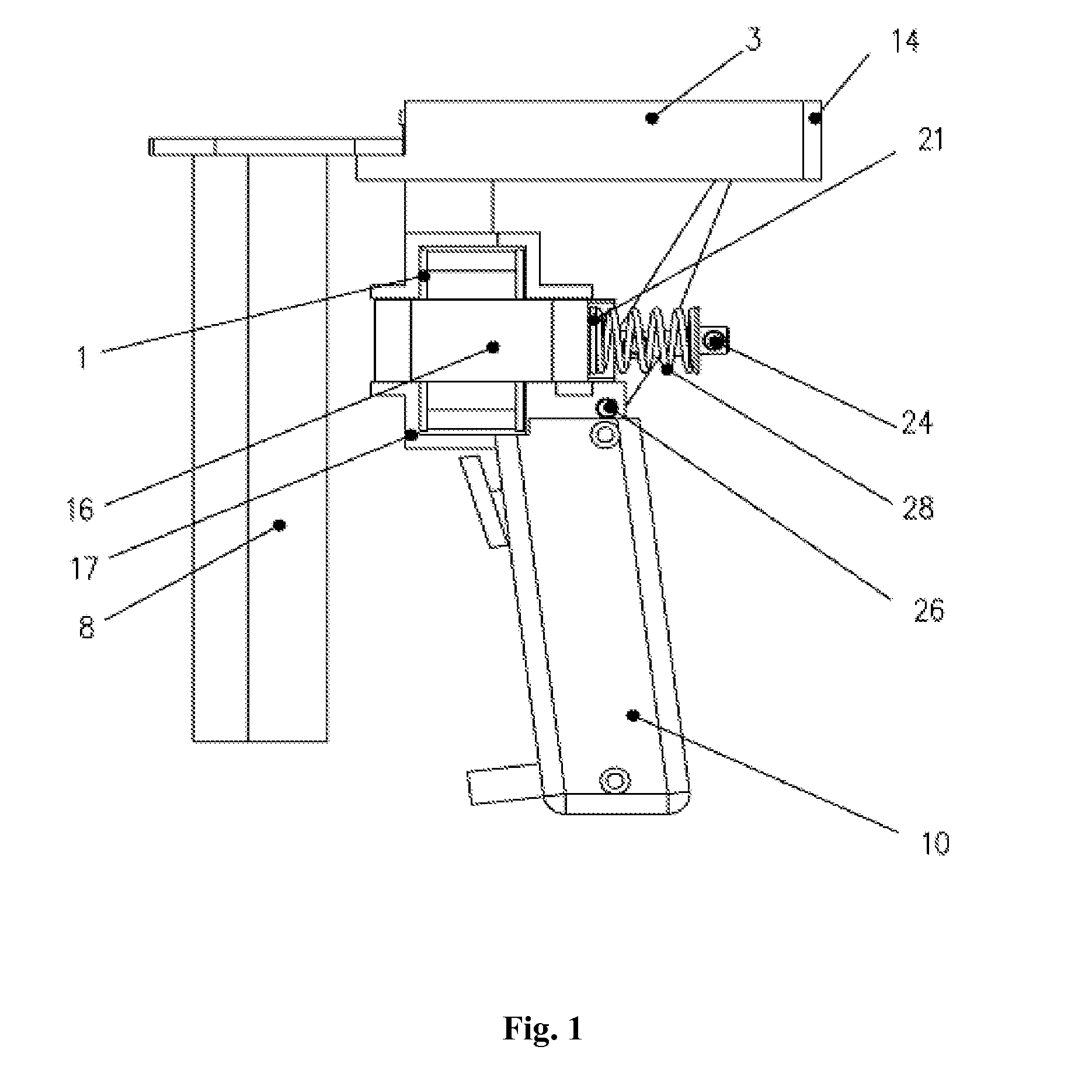
[0012]As shown in FIG. 1 and FIG. 2, a high-speed electromagnetic nail gun mainly comprises a handle 9, an electromagnetic lever driving device, a firing pin slideway 3 and a muzzle magazine assembly 8.

[0013]The upper end of the handle 9 and the lower end of the lever base 17 are connected. The handle 9 is hollow, so that the control circuit board can be set inside. A handle case 10 is provided outside the handle, which encloses all electronic components that are in the handle inside it. A micro-switch 12 for switching on and off the power supply of electromagnetic coils 29 is provided inside the handle. The trigger 11 of the micro-switch is exposed on the upper end of the front part of the handle 9; the trigger is for pressing the switch button of the micro-switch.

[0014]The electromagnetic lever driving device comprises a lever base 17, a coil frame 1, electromagnetic coils 29, an iron core 2, a core linkage 18, a reset spring connecting member 22, a lever 15 and a reset spring 28....


PUM


Abstract

A high-speed electromagnetic nailing gun with a lever, which includes a handle (9), an electromagnetism lever driving device, a ram slideway (3), a muzzle magazine groupware (8). The electromagnetic force is used as the power of the electromagnetic nailing gun, the electromagnetic nailing gun accomplishes nailing by shift-speed driving the ram with the lever (15). It is not necessary for the electromagnetic nailing gun to equip air-pressing accessories, which is convenient to carry, the electromagnetic nailing gun causes little shock and noise when using.

Description

BACKGROUND[0001]1. Field of the Invention[0002]The present invention pertains to a high-speed electromagnetic nail gun with a lever.[0003]2. Description of Related Arts[0004]Pneumatic nail guns are applied widely in fields of construction, renovation, furniture manufacture, advertisement decoration and so on. Currently, the most commonly used driving force for nail guns is compressed air. By compressing air to power an air hammer and drive nails into wall or wood, the purpose of fastening two things together can be accomplished. However, these type of pneumatic nail guns have the disadvantages of being complicated, heavy, expensive to manufacture, high cost, vibrating when used, noisy and etc. not only, but also needs to be equipped with a compressor, a pressure adjustment and gas control device, and pipes and connector assembly that are used for connecting the nail gun and the compressor; therefore, it leads to high cost and inconvenience; moreover, when operating the nail gun, the...

Claims


Application Information

Patent Timeline
Patent Type & Authority Applications(United States)
IPC IPC(8): B25C1/06
CPCB25C1/06
Inventor FENG, ZEZHOULIAO, ZHIWENFAN, YUE
Owner BEIJING DAFENG TECH
Learn More