
Fluidproof connector

a technology of connectors and connectors, applied in the direction of couplings/cases, coupling device connections, securing/insulating coupling contact members, etc., can solve the problems of inner circumferential surfaces of through holes that are not used by workers, and achieve good fluid- or waterproofness

Inactive Publication Date: 2011-04-14
SUMITOMO WIRING SYST LTD
View PDF4 Cites 18 Cited by
  • Summary
  • Abstract
  • Description
  • Claims
  • Application Information

AI Technical Summary

Benefits of technology

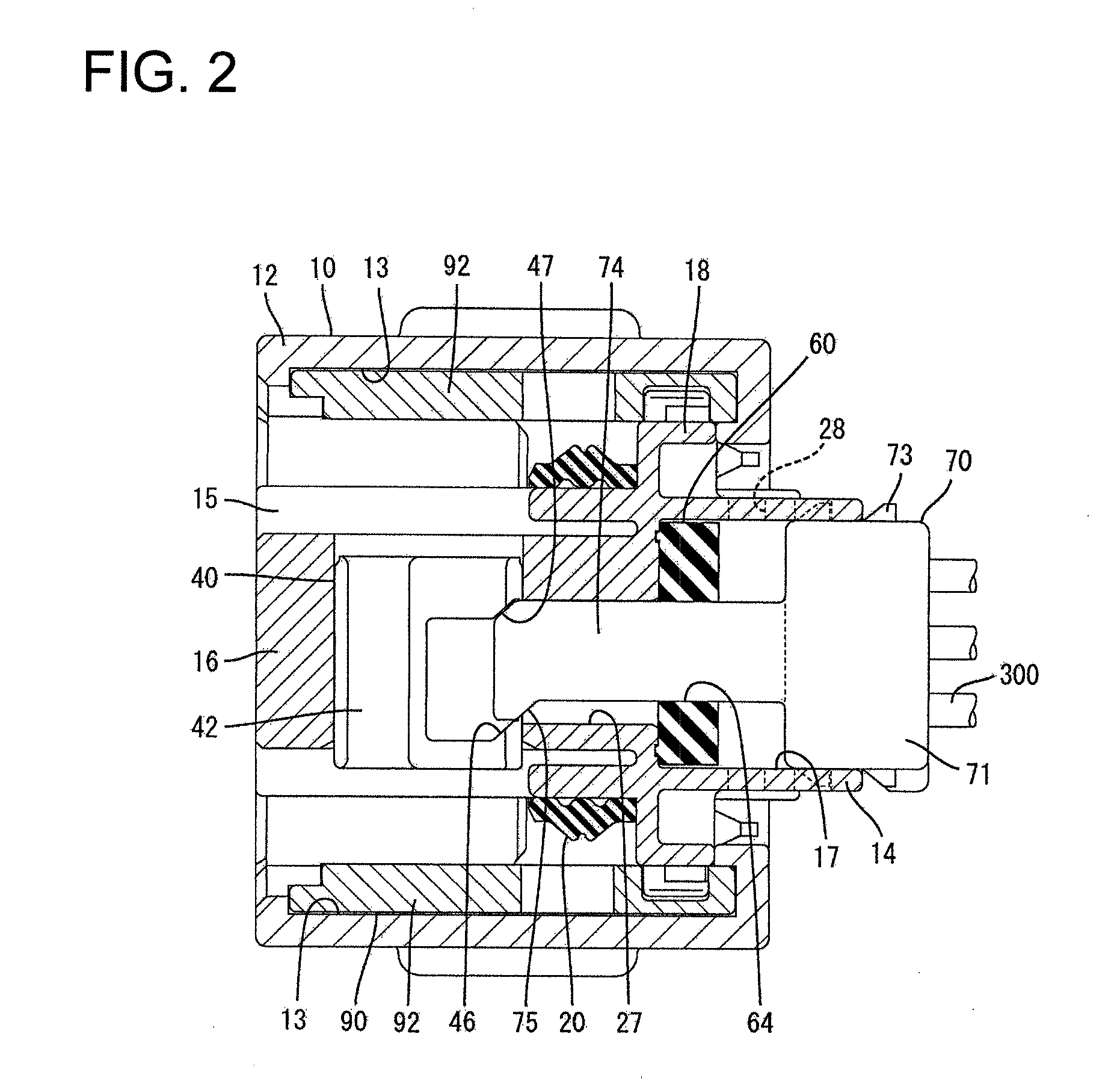
[0009]The unlock link slides in contact with the arm If the resilient plug pressing member can be returned from the pushed-in position to the initial position when withdrawing the terminal fitting from the housing. The retainer can follow this movement of the resilient plug pressing member and moves from the second position to the first position. Further, the unlock link slides in contact with the arm if the retainer can be returned from the second position to the first position. Thus, the resilient plug pressing member can follow this movement of the retainer and returns from the pushed-in position to the initial position. Accordingly, it is not necessary to move the retainer to the first position and separately to move the resilient plug pressing member to the initial position, thereby mitigating a work load and preventing the resilient plug pressing member from being left unmoved.
[0010]The resilient plug pressing member returns to the initial position if the retainer returns to the first position. Thus, a compressed state of the resilient plug is released when withdrawing the terminal fitting, thereby avoiding large frictional resistance between the terminal fitting and the inner surface of the through hole when the terminal fitting passes the through hole. Thus, the terminal fitting will not damage the resilient plug.
[0016]At least one projection may be formed on a front surface of the resilient plug with respect to a mounting direction into the housing and at least one recess may be formed in a surface of the housing to be held in contact with the resilient plug. The projection is squeezed into close contact with an inner surface of the recess at the pushed-in position. The projection and the recess ensure good fluid- or waterproofness.
[0017]The projection and the recess preferably are formed over their entire peripheries of edge portions of the respective surfaces of the resilient plug and the housing. Thus, the housing is sealed completely around the periphery to achieve better fluid- or waterproofness.

Problems solved by technology

Workers are not accustomed to moving the rubber plug, and hence may forget to move the rubber plug unit to the initial position when the retainer is moved to the partial locking position.
Then, the terminal fittings have to pass the narrow through holes of the rubber plug in a compressed state, and the inner circumferential surfaces of the through holes might be damaged by interference with the terminal fittings.

Method used


Image

  • Fluidproof connector
  • Fluidproof connector
  • Fluidproof connector

Examples


Embodiment Construction

[0032]A waterproof connector in accordance with the invention is illustrated in FIGS. 1 to 12. This waterproof connector has a housing 10, a retainer 40, a rubber plug 60, a rubber plug pressing member 70, a movable member, such as a lever 90, and terminal fittings 100. The housing 10 is connectable with a mating housing 200. In the following description, an end to be connected with the mating housing 200 is referred to as the front end concerning forward and backward directions.

[0033]The housing 10 is made e.g. of synthetic resin and has an inner housing 11 and an outer housing 12 separable from each other. The outer housing 12 is a generally wide rectangular tube with open front and rear ends. Two unillustrated engaging portions are formed on the inner surfaces of opposite side walls of the outer housing 12. Further, two entrance holes 13 are formed at upper and lower ends of one side wall of the outer housing 12.

[0034]The lever 90 is made e.g. of synthetic resin and has a substan...


PUM


Abstract

A retainer (40), a rubber plug (60) and a rubber plug pressing member (70) are mounted in a housing (10). The retainer (40) is movable between a partial locking position and a full locking position, and the rubber plug pressing member (70) is movable between an initial position and a pushed-in position. The rubber plug pressing member (70) is formed with arm portions (74) projecting therefrom. The retainer (40) is formed with unlock linking portions (46) for linking a movement of this retainer (40) from the full locking position to the partial locking position and a movement of the rubber plug pressing member (70) from the pushed-in position to the initial position with each other by coming into sliding contact with the arm portions (74).

Description

BACKGROUND OF THE INVENTION[0001]1. Field of the Invention[0002]The invention relates to a fluidproof connector.[0003]2. Description of the Related Art[0004]U.S. Pat. No. 6,071,147 discloses a waterproof connector with a housing, a retainer, a rubber plug, a rear cover and terminal fittings. The housing is formed with cavities for receiving the terminal fittings. The retainer is movable between a partial locking position and a full locking position. The retainer includes retaining portions that are retracted from the cavities at the partial locking position to permit insertion and withdrawal of the terminal fittings into and from the cavities. However, the retaining portions enter the cavities at the full locking position to retain the terminal fittings. The rubber plug is formed with through holes, into which wires connected with the terminal fittings are inserted after the passage of the terminal fittings.[0005]The rubber plug and the rear cover are united to form a rubber plug un...

Claims


Application Information

Patent Timeline
Patent Type & Authority Applications(United States)
IPC IPC(8): H01R13/52
CPCH01R13/4362H01R13/62911H01R13/5208
Inventor YOSHIOKA, CHIKAHIROKOBAYASHI, TOMOHIKOHIRANO, SHINJIITOU, MASATOSHI
Owner SUMITOMO WIRING SYST LTD
Learn More