
Method and Apparatus for Conveying Precoding Information in a MIMO System

Active Publication Date: 2011-04-14
TELEFON AB LM ERICSSON (PUBL)
View PDF3 Cites 102 Cited by
  • Summary
  • Abstract
  • Description
  • Claims
  • Application Information

AI Technical Summary

Benefits of technology

It is an object of the present invention to generally address the problems outlined above. Further, it is an object to provide a solution that enables a reduced signalling overhead when conveying precoder related information from a sending node to a receiving node, and / or improved efficiency and flexibility for spatial multiplexing. These objects and others may be accomplished by a method and apparatus according to the attached independent claims.

Problems solved by technology

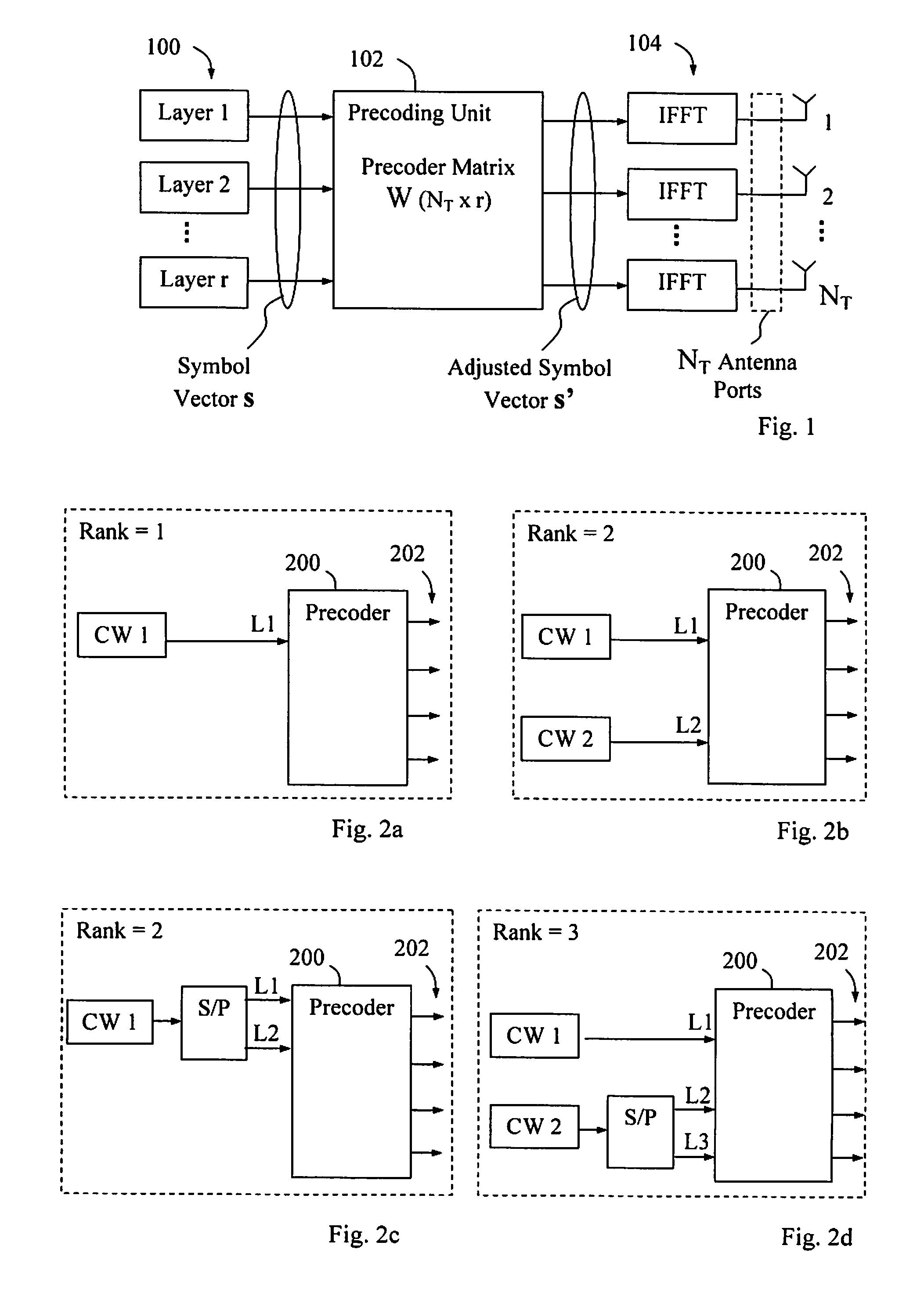
Hence, if the current channel rank is only one when simultaneously transmitting two codewords mapping to two separate layers, i.e. using a transmission rank of two, the two signals corresponding to the codewords will most likely interfere so much that both codewords are erroneously detected at the receiving node.
However, it is a drawback in the existing ways of conveying MIMO and precoder related information from a sending node to a receiving node, as exemplified by the above-mentioned PDCCH, that a large signalling overhead is required.
As a result, the coverage of control signalling may be seriously reduced, implying that control channel coverage may well be a limiting factor in the use of MIMO.
Furthermore, no efficient support has been provided for so-called transmission rank override in the above-described precoder confirmation.
In addition, when a HARQ process is originally transmitted mapped to two layers using transmission rank 3 or 4, that HARQ process cannot efficiently provide for retransmission if the transmission rank is reduced to 2 due to fluctuating channel properties.
Hence, it is generally a problem that the payload for conveying MIMO and precoder related information, e.g. transmission rank indicator (TRI), precoder confirmation, explicit precoder matrix indicator (PMI), from a signal sending node to a signal receiving node is typically large and requires substantial signalling bandwidth.

Method used


Image

  • Method and Apparatus for Conveying Precoding Information in a MIMO System
  • Method and Apparatus for Conveying Precoding Information in a MIMO System
  • Method and Apparatus for Conveying Precoding Information in a MIMO System

Examples


Embodiment Construction

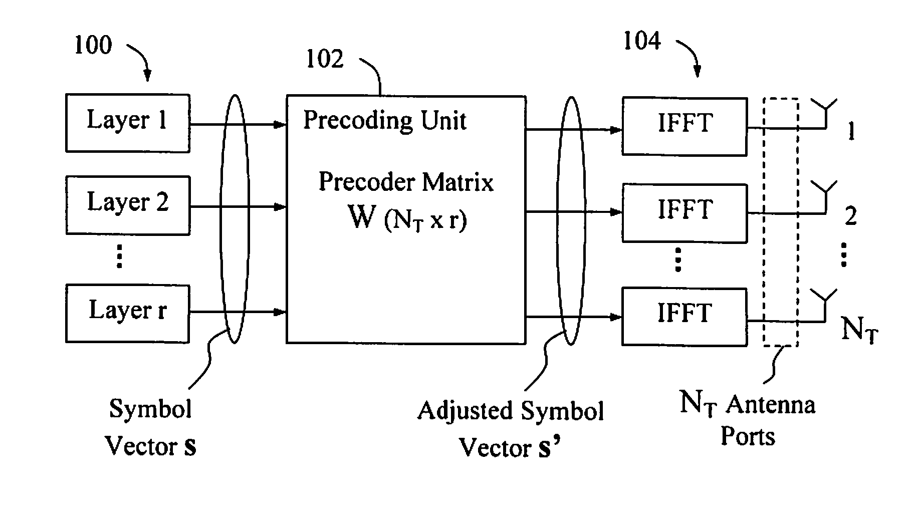
The present invention can be used to reduce the signalling overhead needed for precoder signalling, and / or to provide improved flexibility for conveying precoder related information, as follows. It can also be used to utilise any available limited signalling space more efficiently, e.g. within prevailing header size restrictions dictated by any standard protocol(s) used.

It is assumed that one node is obliged to send control information to another node that describes the properties of an associated wireless data transmission between the nodes, and that the control information should include fields with information on the payload size of this associated data transmission. These fields are generally denoted “payload size related fields” in this description.

Briefly described, existing payload size related fields in a control message conveyed from a first node to a second node, carrying information on the payload size of an associated data transmission that the control message refers to,...


PUM


Abstract

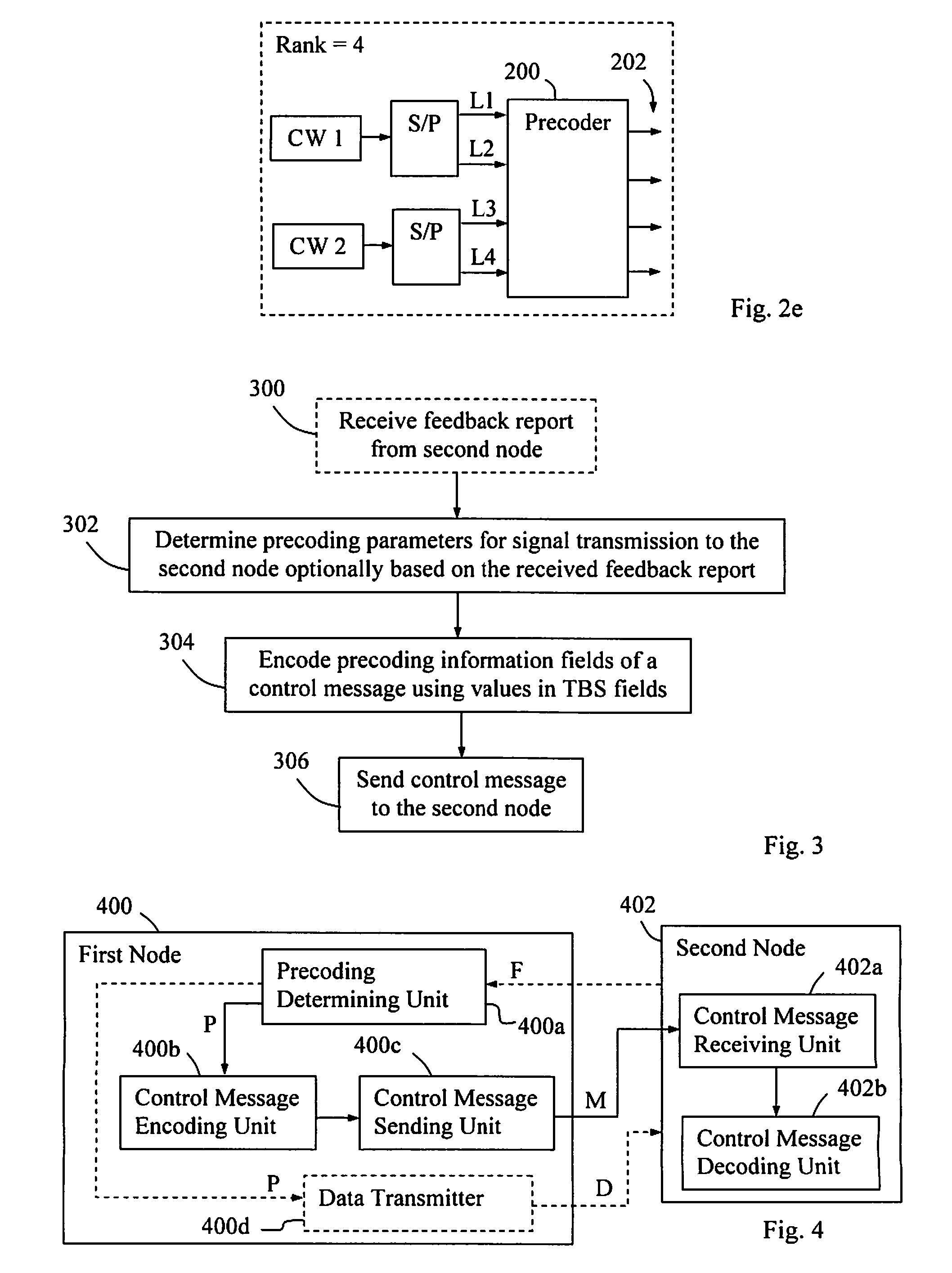
Method and apparatus for conveying precoding information in a control message from a first node to a second node, with information on properties of an associated wireless data transmission (D) between the first and second nodes employing spatial multiplexing and precoding for the data transmission. The first node determines precoding parameters for signal transmission to the receiving node, optionally based on feedback reports from the receiving node. The first node encodes control information bits in precoding information fields of the control message by means of values in TBS fields of the control message, such that the TBS field values determine the interpretation of the bits in the precoding information field(s). The control message is then sent to the second node.

Description

TECHNICAL FIELDThe present invention relates generally to a method and apparatus for supporting wireless transmissions in a telecommunication system when multiple antennas are used.BACKGROUNDIn 3GPP (3rd Generation Partnership Project), the packet-switched communication systems LTE (Long Term Evolution) and HSPA (High Speed Packet Access) have been specified for wireless transmission of data packets between user terminals and base stations in a cellular / mobile network. LTE and other systems generally use OFDM (Orthogonal Frequency Division Multiplexing) involving multiple closely spaced orthogonal sub-carriers, which is a well-known technique in the art. The sub-carriers are further divided into timeslots where each frequency / timeslot combination is referred to as a resource element.In this description, a “sending node” is a node which sends information carrying signals over a wireless link, and a “receiving node” is a node which receives and hopefully detects those signals. In the ...

Claims


Application Information

Patent Timeline
IPC IPC(8): H04B7/02H04W72/00
CPCH04B7/0413H04B7/0456H04B7/0697
Inventor JONGREN, GEORGE
Owner TELEFON AB LM ERICSSON (PUBL)
Learn More