Exterior Solar Shading With Light Redirection
a solar shading and light technology, applied in the direction of instruments, constructions, building components, etc., can solve the problems of health and safety problems, waste of energy, and limited usefulness of solar shading louvers,
- Summary
- Abstract
- Description
- Claims
- Application Information
AI Technical Summary
Benefits of technology
Problems solved by technology
Method used
Image

Examples
third embodiment
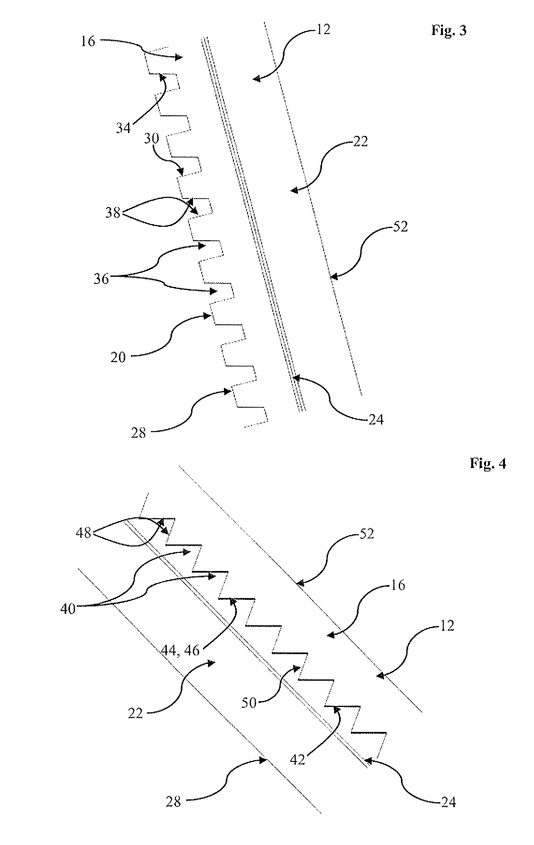
[0034]In this third embodiment, direct reflection is mainly utilised as opposed to, typically total, internal reflection as in the prior embodiments. To this end, the upper side wall 44 of each groove 40 includes a discrete reflector 46. The reflector 46 is preferably a mirrored or silvered surface, and is preferably opaque but may be semi-transparent. This therefore functions as a partial micro-blind, providing physical direct shading. The reflector 46 is typically applied following formation of the grooves 40 and faces into the light-redirecting layer 16. In this case, both side walls 48 of each groove 40 may be covered with the reflector material, and then the grooves 40 are re-machined to grind or remove the reflector 46 from the lower side wall 50.
[0035]This arrangement can be reversed, and when the light-redirecting layer is on the bottom, the reflector would face towards the support layer thereabove.
[0036]The reflector 46 is conveniently protected by being positioned internal...
fourth embodiment
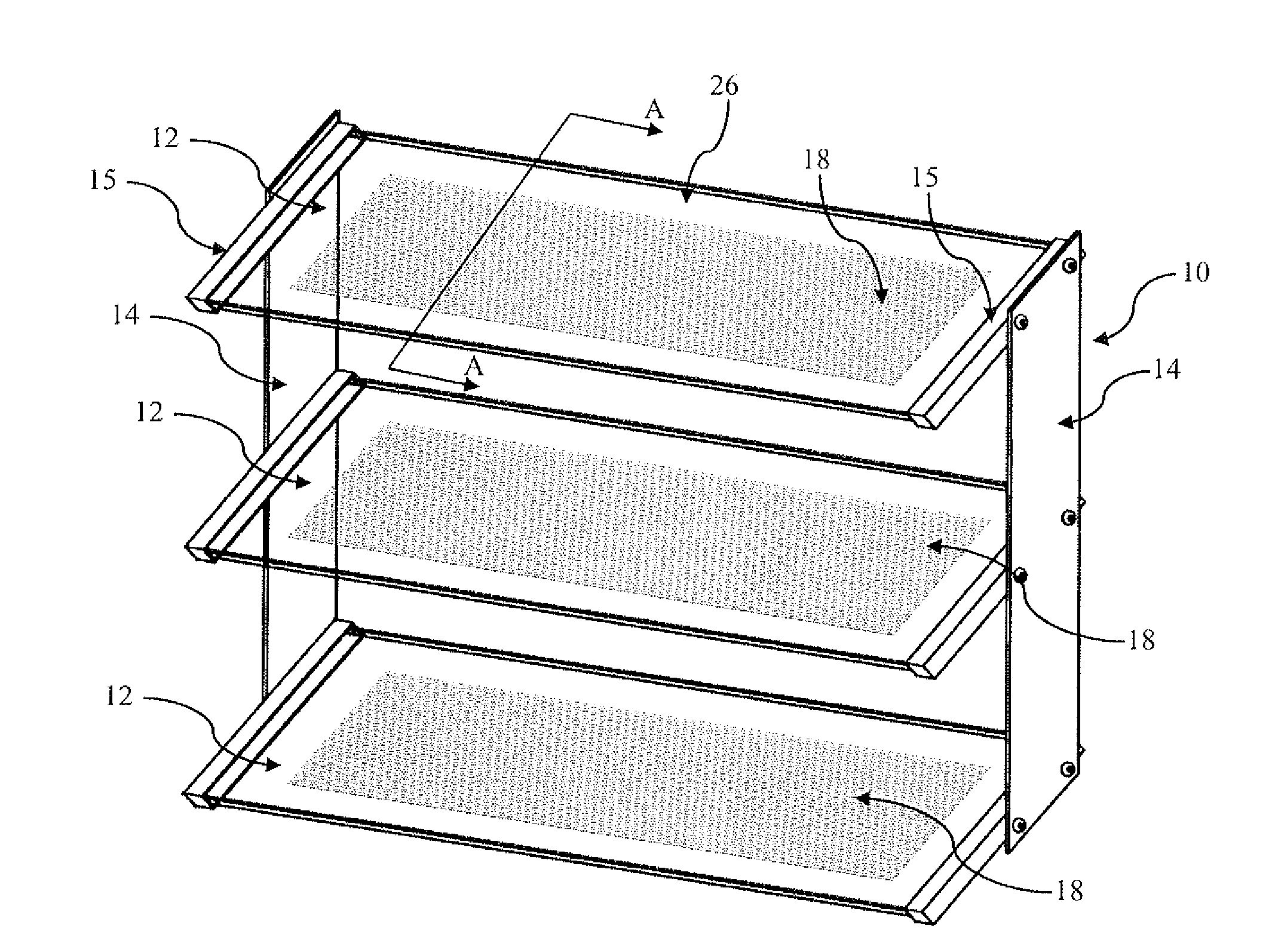
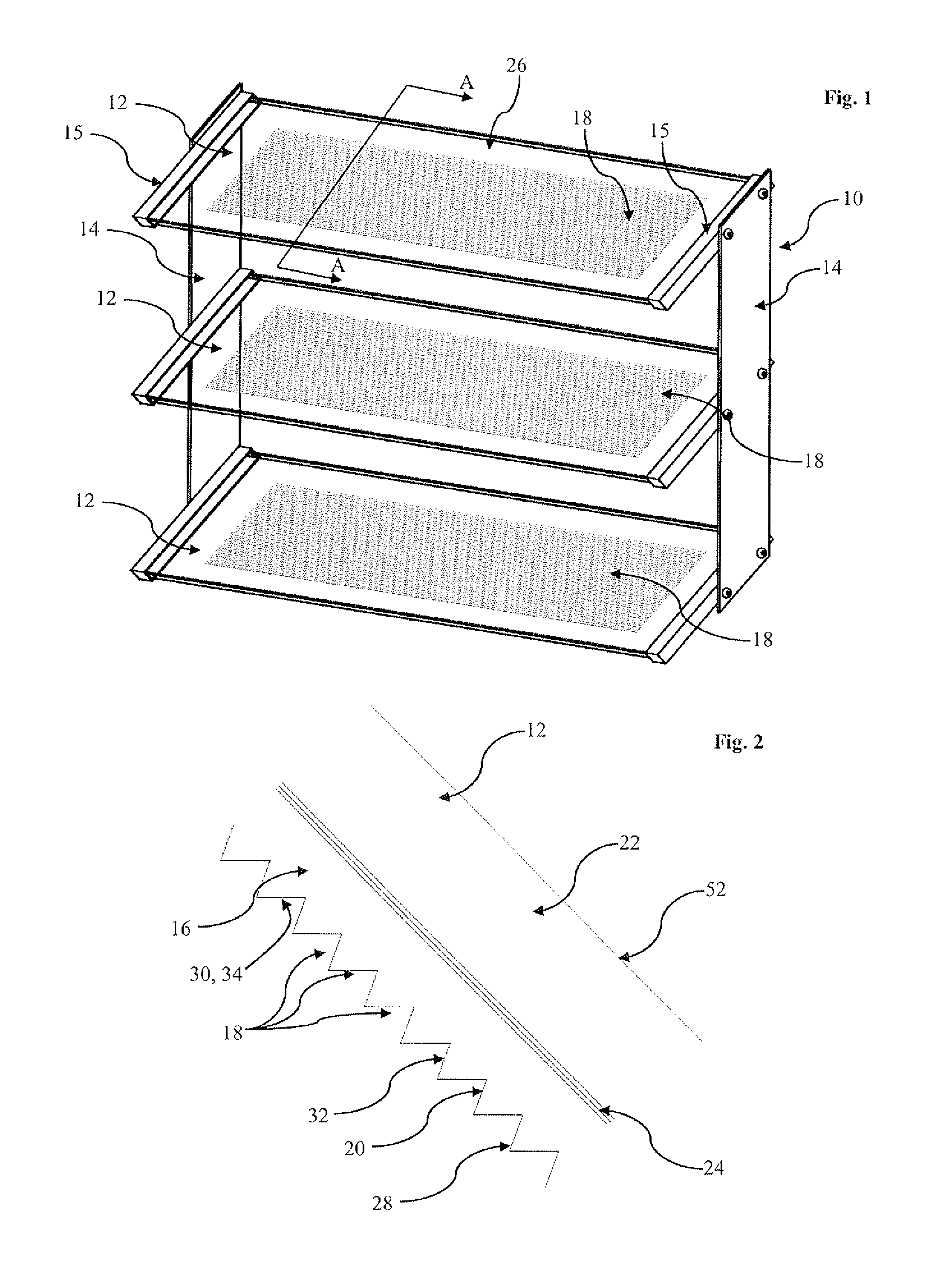
[0043]Referring now to FIG. 5, there is shown a plan view of a louver 12 of exterior solar shading 10. Like references refer to like parts and further detailed description is omitted.
[0044]In this embodiment, the grooves 18, 36, 40 are shaped and formed as described above. However, rather than having a single group of grooves 18, 36, 40, a plurality of groups 54 of grooves 18, 36, 40 are provided in spaced apart relationship. This is beneficial in that it improves the structural strength of louver 12.
fifth embodiment
[0045]As shown in FIG. 6, which depicts exterior solar shading 10, the grooves 18, 36, 40 may be arcuate rather than rectilinear. In this case, the grooves 18, 36, 40 are again split into groups 54, and the overall arcuate nature of the grooves 18, 36, 40 is generally sinusoidal. It will be appreciated in FIG. 6, that the groups 56 of grooves 18, 36, 40 on the one side of the louver 12 describe a concave shape, whilst the groups 58 of grooves 18, 36, 40 on the other side describe a convex shape.
[0046]In the fourth and fifth embodiments, rather than having groups of grooves which are spaced apart in the lateral and longitudinal directions, it is possible to have groups of grooves which are only spaced apart in one of the lateral and longitudinal directions.
PUM
 Abstract
Description
Claims
Application Information
 - R&D
- Intellectual Property
- Life Sciences
- Materials
- Tech Scout
- Unparalleled Data Quality
- Higher Quality Content
- 60% Fewer Hallucinations
Browse by: Latest US Patents, China's latest patents, Technical Efficacy Thesaurus, Application Domain, Technology Topic, Popular Technical Reports.
© 2025 PatSnap. All rights reserved.Legal|Privacy policy|Modern Slavery Act Transparency Statement|Sitemap|About US| Contact US: help@patsnap.com