
Medical clot treatment device with distal filter

a treatment device and filter technology, applied in the field of medical devices, can solve the problems of severe health problems, brain oxygen supply, particularly dangerous, etc., and achieve the effect of preserving the cage assembly shape and integrity, and preserving the ability

Inactive Publication Date: 2011-04-07
STRYKER EURO OPERATIONS HLDG LLC +1
View PDF99 Cites 129 Cited by
  • Summary
  • Abstract
  • Description
  • Claims
  • Application Information

AI Technical Summary

Benefits of technology

The device effectively navigates tortuous vasculature, displaces or removes emboli, and restores blood flow, even in challenging anatomical locations like the middle cerebral artery, while minimizing vessel damage and ensuring safe removal of clot fragments.

Problems solved by technology

They are particularly dangerous if the emboli passes to the brain and causes an embolic stroke.
Obviously, when blood flow is inhibited or cut off completely from a portion of the brain, the brain's oxygen supply is limited causing severe health problems.
The lodging of thrombus in various sites is often complicated by the presence of atherosclerosis.
This disease causes the vessels to become tortuous and narrowed.
Clots occurring in these diseased vessels are difficult to remove using balloon or Fogarty catheters.
Removal of emboli using balloon catheters is rife with potential problems.
One such problem occurs during removal of a clot.
The resistance to such removal often causes the balloon portion of the catheter to evert over the tip of the catheter.
Should the user need to partially deflate the balloon during such a deflation, the distal tip of the balloon may become distended and angulate.
Another difficulty with balloon catheters is the possibility of damage to the intima of arteries.
In the worst case, the balloon may rupture leaving balloon portions in the bloodstream.

Method used


Image

  • Medical clot treatment device with distal filter
  • Medical clot treatment device with distal filter
  • Medical clot treatment device with distal filter

Examples


Embodiment Construction

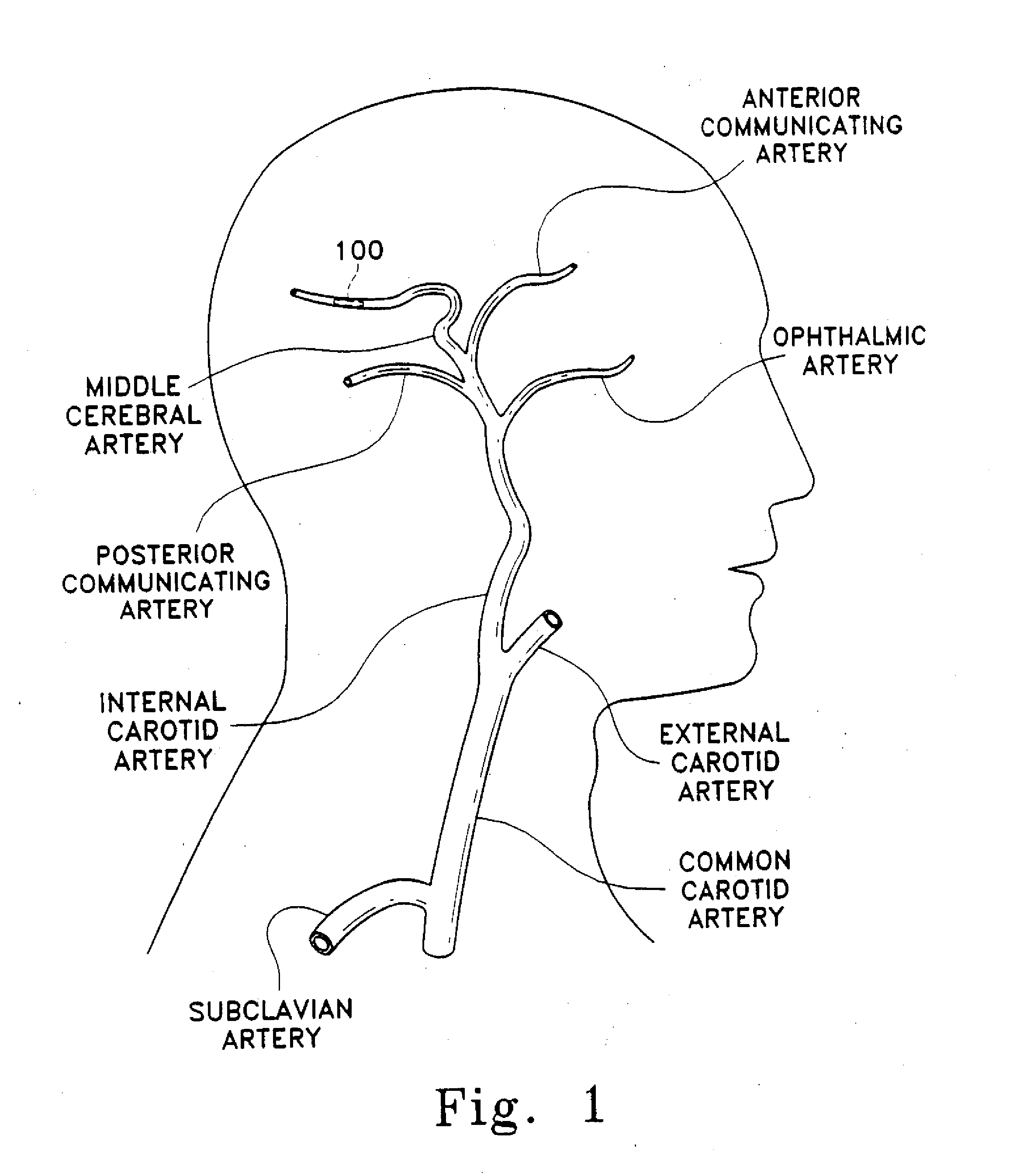
[0033]This device is a surgical implement. It is designed variously to move a thrombus aside and provide a fluid passageway along that thrombus or to penetrate and at least partially to retrieve emboli situated in human vasculature. It is intended to be used rapidly as a flow restoration device. Even in those instances where the embolism is not or cannot be completely removed, this inventive device is believed to be useful in displacing, extracting, or removing a portion of the clot and thereby permitting restoration of partial blood flow. It can be used to move the clot to a more advantageous site in the body. It is suitably flexible to be placed in the distal tortuous vasculature of the brain and hence is useful in treating blocking emboli found there. This device may be considered a partial treatment for embolic stroke, for instance, when used with the addition of thrombolytics.

[0034]As a matter of practical experience, a large proportion of emboli sloughed into the brain are sel...


PUM


Abstract

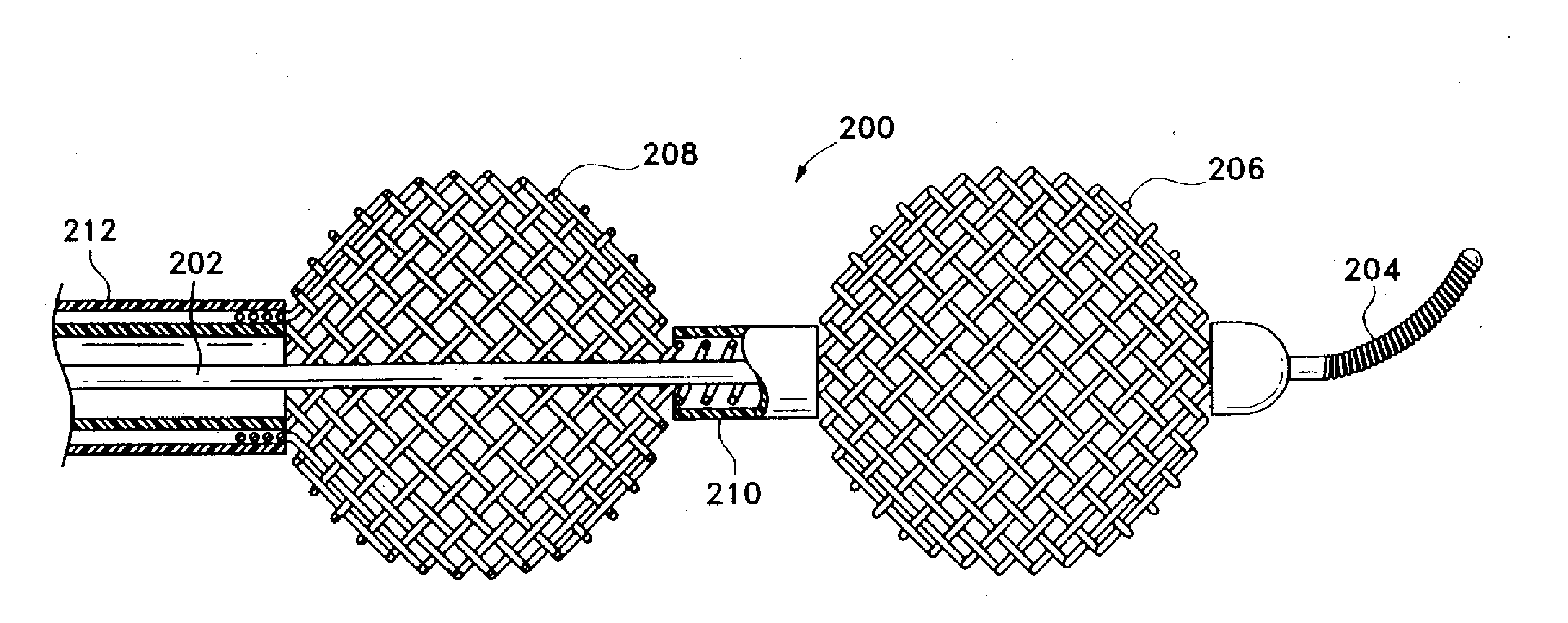
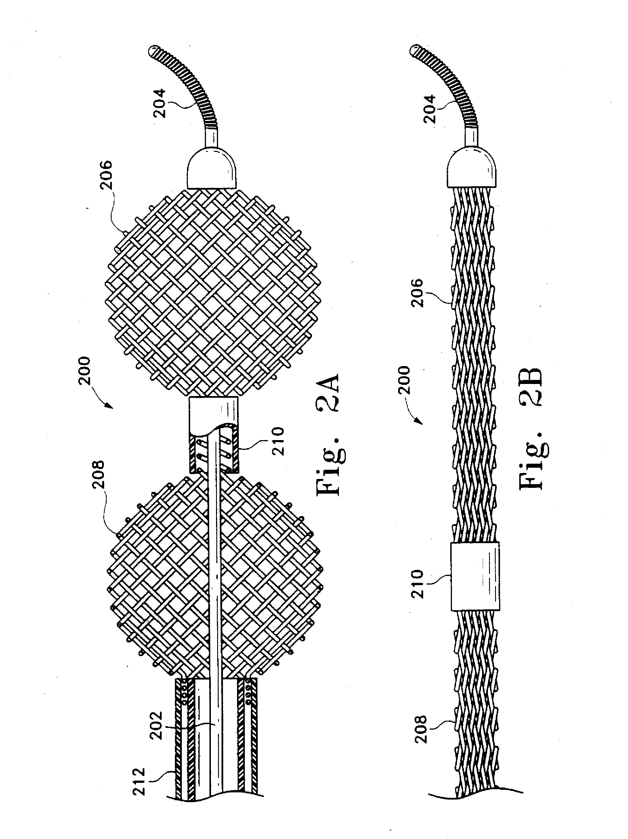
This is a surgical device usually delivered through an intravascular catheter. It may be used in several ways. It may, for instance, be used to open a clear passageway adjacent thrombus to allow both blood and medication to bypass the clot. It may be used to pierce and to remove thrombus. These thrombus are often found in tortuous vasculature. The device includes several sections. The device has a core element, typically a core wire. Placed around the distal end of the core element is a collapsible but preferably self expanding proximal cage assembly and a distal filter, preferably a self-expanding cage assembly or other filter component. The various portions of those components are preferably radio-opaque. The proximal end of the proximal cage is typically is affixed to an actuator in such a way as to allow expansion of the cage after deployment. The proximal cage assembly may be used for collecting emboli or for displacing them to allow blood flow to resume, either with or without concurrent clot-dissolving drug treatment. The distal sector, whether a self-expanding cage or fan, is placed distally of the thrombus to collect portions of the thrombus which may loosen during the treatment or removal procedure.

Description

CROSS REFERENCE TO RELATED PATENT APPLICATION[0001]This application is a continuation of U.S. patent application Ser. No. 10 / 082,492, filed Feb. 22, 2002, which is a continuation of U.S. patent application Ser. No. 09 / 452,528, filed Dec. 1, 1999, now U.S. Pat. No. 6,383,205, which is a continuation of U.S. patent application Ser. No. 08 / 941,514, filed Sep. 30, 1997, now U.S. Pat. No. 6,066,149, the entirety of which is hereby incorporated by reference.FIELD OF THE INVENTION[0002]This is a medical device used to treat embolic strokes. In particular, it is a surgical device usually delivered through an intravascular catheter. It may be used in several ways. It may, for instance, be used to open a clear passageway adjacent a thrombus to allow both blood and medication to bypass the clot. It may be used to pierce and to remove a thrombus. These thrombi are often found in tortuous vasculature. The device may include several sections: an elongated core element, a proximal cage assembly, a...

Claims


Application Information

Patent Timeline
Patent Type & Authority Applications(United States)
IPC IPC(8): A61F2/01A61B17/22A61B19/00
CPCA61B17/221A61F2230/0071A61B2017/22034A61B2017/22045A61B2017/22084A61B2017/2212A61B2019/5238A61F2/01A61F2/013A61F2002/011A61F2002/016A61F2230/0006A61F2230/005A61F2230/0067A61B19/54A61B90/39A61B2090/376A61F2/0108A61F2/011
Inventor SAMSON, GENECARRISON, HAROLD F.
Owner STRYKER EURO OPERATIONS HLDG LLC
Learn More