Eureka AIR delivers breakthrough ideas for toughest innovation challenges, trusted by R&D personnel around the world.

MRI Compatible Leadless Cardiac Pacemaker

a leadless, cardiac pacemaker technology, applied in the direction of heart stimulators, internal electrodes, therapy, etc., can solve the problems of unsafe mri, ventricular fibrillation, tachycardia,

Inactive Publication Date: 2011-03-31
NANOSTIM
View PDF101 Cites 232 Cited by
  • Summary
  • Abstract
  • Description
  • Claims
  • Application Information

AI Technical Summary

Benefits of technology

[0028]Another aspect of the invention provides a method of obtaining an MRI image of a patient, the patient having an implanted battery powered leadless biostimulator, the method comprising generating a static magnetic field, a pulsed gradient field, and an RF field in the patient, maintaining safe operation of the leadless biostimulator within the patient in the presence of the static magnetic field, the gradient field, and the RF field without attenuating or eliminating a signal in the leadless biostimulator.

Problems solved by technology

However, the use of MRI is contraindicated by pacemaker manufacturers since MRI can be unsafe for patients with implanted pacemakers.
This switch from normal inhibited mode pacing to asynchronous mode pacing can result in tachycardia leading to ventricular fibrillation should the pacemaker fire into the “vulnerable phase” of the cardiac cycle.
Induced currents and voltages in a pacemaker can cause inappropriate sensing and triggering and even stimulation.
The RF field can result in tissue heating at the site of the electrode tip of an implanted pacemaker.
A pacemaker in the MRI field can also distort the field creating image artifacts.

Method used


Image

  • MRI Compatible Leadless Cardiac Pacemaker
  • MRI Compatible Leadless Cardiac Pacemaker
  • MRI Compatible Leadless Cardiac Pacemaker

Examples


Embodiment Construction

[0037]In some embodiments of a leadless biostimulator, a leadless cardiac pacemaker can communicate by conducted communication, representing a substantial departure from the conventional pacing systems. For example, an illustrative cardiac pacing system can perform cardiac pacing that has many of the advantages of conventional cardiac pacemakers while extending performance, functionality, and operating characteristics with one or more of several improvements.

[0038]In a particular embodiment of a cardiac pacing system, cardiac pacing is provided without a pulse generator located in the pectoral region or abdomen, without an electrode-lead separate from the pulse generator, without a communication coil or antenna, and without an additional requirement on battery power for transmitted communication.

[0039]Various embodiments of a system comprising one or more leadless cardiac pacemakers or biostimulators are described. An embodiment of a cardiac pacing system configured to attain these ...


PUM


Abstract

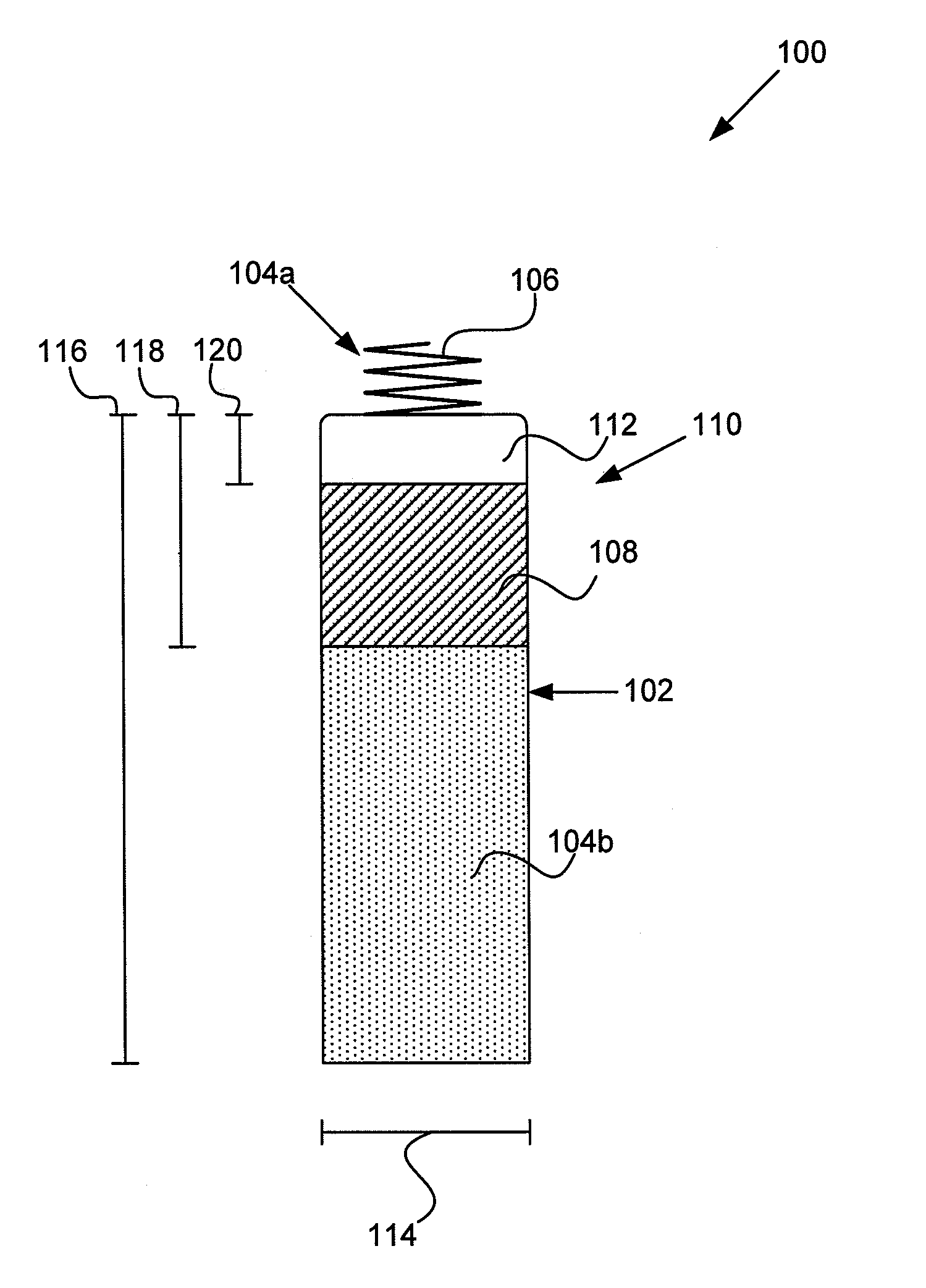
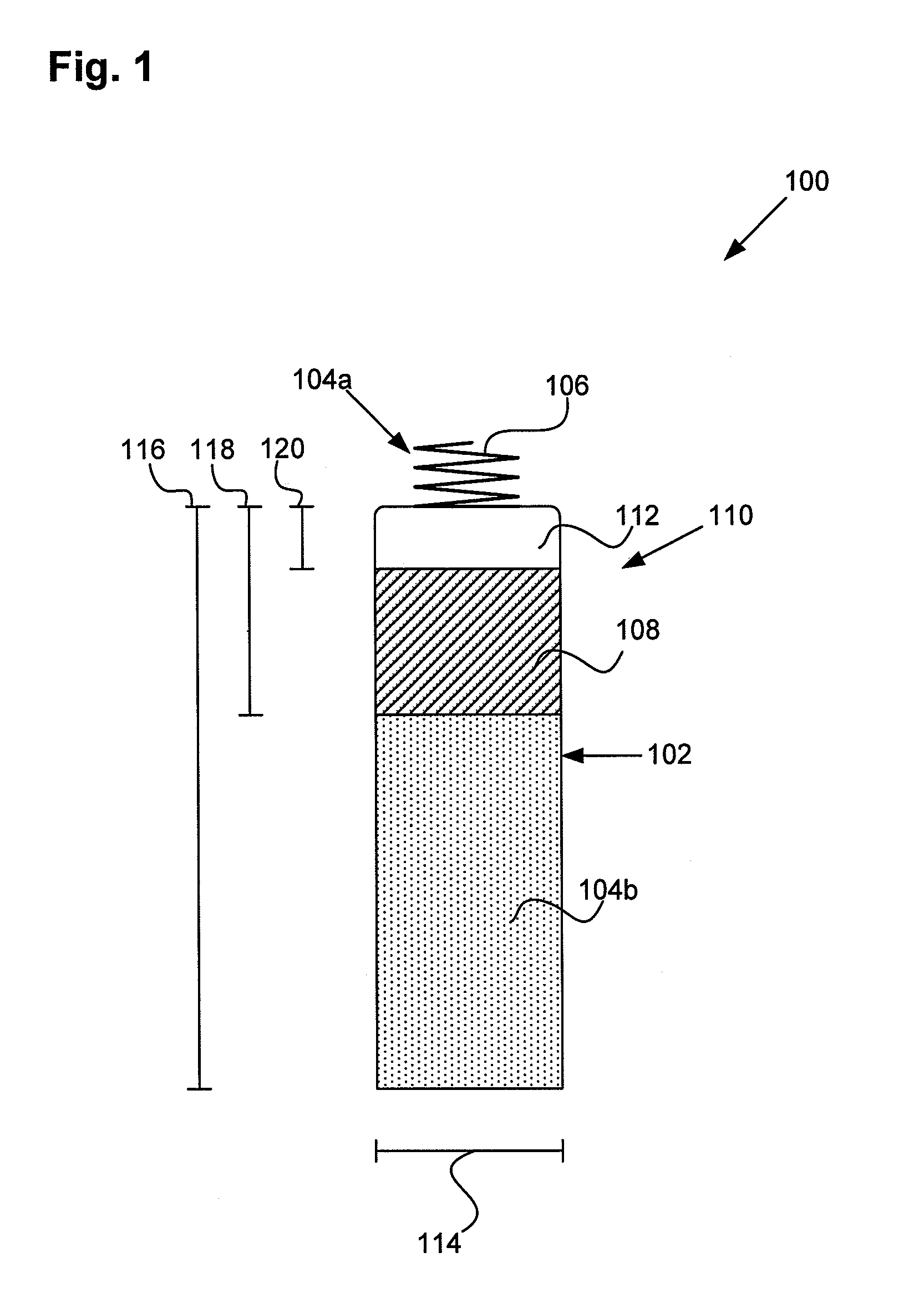
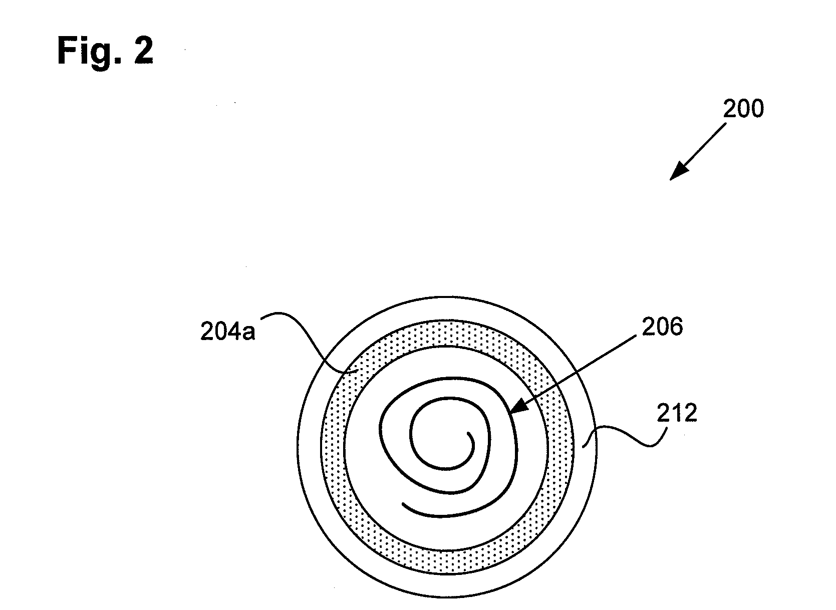
An implantable battery powered leadless pacemaker or biostimulator is provided that may include any of a number of features. One feature of the biostimulator is that it safely operates under a wide range of MRI conditions. One feature of the biostimulator is that it has a total volume small enough to avoid excessive image artifacts during a MRI procedure. Another feature of the biostimulator is that it has reduced path lengths between electrodes to minimize tissue heating at the site of the biostimulator. Yet another feature of the biostimulator is that a current loop area within the biostimulator is small enough to reduce an induced current and voltage in the biostimulator during MRI procedures. Methods associated with use of the biostimulator are also covered.

Description

INCORPORATION BY REFERENCE[0001]All publications and patent applications mentioned in this specification are herein incorporated by reference to the same extent as if each individual publication or patent application was specifically and individually indicated to be incorporated by reference.FIELD OF THE INVENTION[0002]The present invention relates to leadless cardiac pacemakers, and more particularly, to operating leadless cardiac pacemakers safely in a patient over a wide range of MRI conditions.BACKGROUND OF THE INVENTION[0003]Magnetic Resonance Imaging (MRI) has become an important diagnostic tool used by physicians. However, the use of MRI is contraindicated by pacemaker manufacturers since MRI can be unsafe for patients with implanted pacemakers.[0004]MRI generates cross-sectional images of the human body by first aligning hydrogen nuclei (protons) in one of two possible orientations using a strong, uniform, static magnetic field. Next a radio frequency (RF) signal at the appr...

Claims


Application Information

Patent Timeline
IPC IPC(8): A61N1/362A61N1/375
CPCA61N1/3718A61N1/3756A61N1/0573A61N1/059A61N1/37205
Inventor OSTROFF, ALAN
Owner NANOSTIM
Why Eureka
Eureka Blog
Learn More