
Compound-eye image pickup apparatus

a pickup apparatus and compound eye technology, applied in the field of compound eye image pickup apparatus, can solve the problems of shortening the search time, unable to detect the pickup device, and requiring a long time for the lens to come into focus, so as to achieve the effect of acquiring in a short time the focusing position

Inactive Publication Date: 2011-03-31
FUJIFILM CORP
View PDF9 Cites 30 Cited by
  • Summary
  • Abstract
  • Description
  • Claims
  • Application Information

AI Technical Summary

Benefits of technology

[0011]In order to solve this problem, a method of expanding the AF search range of the left lens which is out of focus to a macro region can be conceived. However, this method is against the purpose of avoiding searching the macro region and limiting the AF search range to a range from the MOD to the telephoto side, that is, shortening the search time, and hence there arises a problem that it takes time before a lens comes into focus.
[0028]According to the presently disclosed subject matter, even when there occurs a problem that the focusing position of only a part of image pickup devices cannot be acquired due to the individual variability in image pickup device, it is possible to acquire in a short time the focusing position of the image pickup device whose focusing position cannot be acquired.

Problems solved by technology

However, the arts described in Japanese Patent Application Laid-Open Nos. 07-67023, 2005-173270, and 2006-162990 presuppose that the focusing positions of both of the two image pickup devices can be obtained, and do not assume a case where, due to the individual variability in the image pickup device, the focusing position of one of the image pickup devices can be detected, whereas the focusing position of another one of the image pickup devices cannot be detected.
However, the environment in which the compound-eye image pickup apparatus is used is not always at normal (room) temperature, and the compound-eye image pickup apparatus is used also at high temperature and low temperature.
However, this method is against the purpose of avoiding searching the macro region and limiting the AF search range to a range from the MOD to the telephoto side, that is, shortening the search time, and hence there arises a problem that it takes time before a lens comes into focus.

Method used


Image

  • Compound-eye image pickup apparatus
  • Compound-eye image pickup apparatus
  • Compound-eye image pickup apparatus

Examples


first embodiment

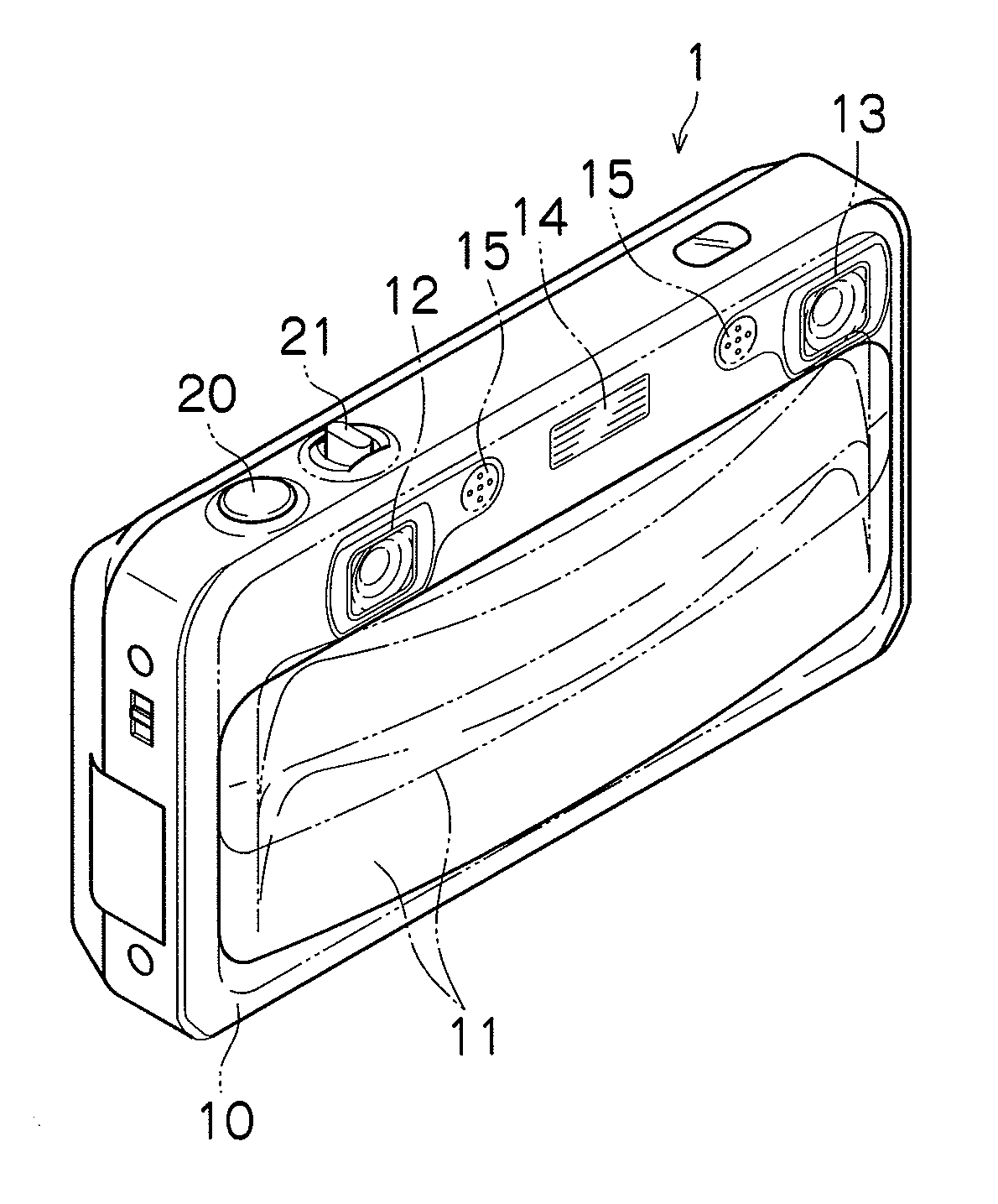
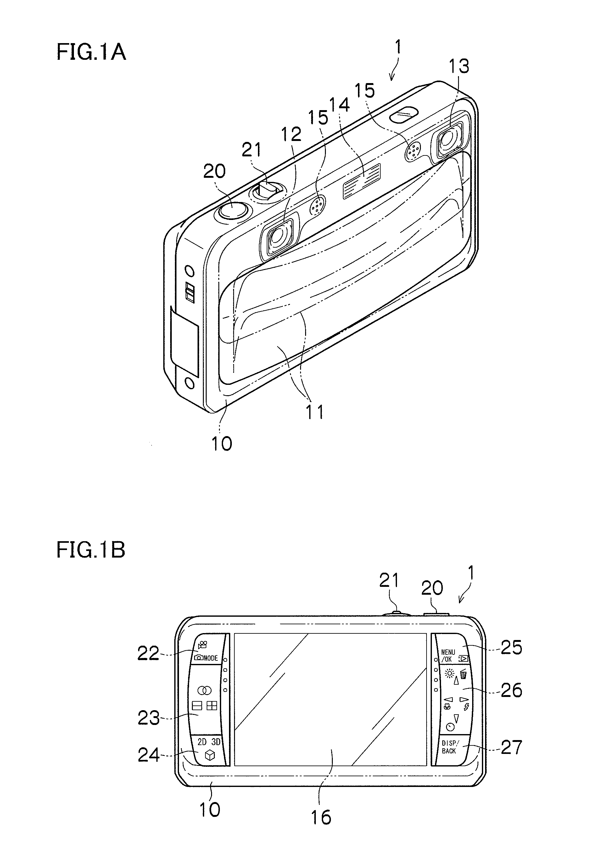
[0046]FIGS. 1A and 1B are external views each illustrating a compound-eye image pickup apparatus 1 which is the compound-eye image pickup apparatus according to the presently disclosed subject matter. FIG. 1A is a front perspective view thereof, and FIG. 1B is a back view thereof. The compound-eye image pickup apparatus 1 includes a plurality of (for example, two in FIGS. 1A and 1B) image pickup systems, and is capable of photographing a stereoscopic image obtained by viewing the same subject at a plurality of points of view (for example, two right and left points of view in FIGS. 1A and 1B) and a single-viewpoint image (two-dimensional image). In addition, the compound-eye image pickup apparatus 1 is capable of not only photographing a still image but also recording and reproducing a moving image and a sound.

[0047]A camera body 10 of the compound-eye image pickup apparatus 1 is formed into a substantial rectangular parallelepiped box-like shape, and as illustrated in FIG. 1A, a bar...

second embodiment

[0126]According to the first embodiment of the presently disclosed subject matter, in the case where the focusing position of any one of the right and left image pickup systems is not detected by the normal AF process, the additional search range is calculated on the basis of the focusing curve, but a method of calculating the additional search range is not limited thereto.

[0127]According to a second embodiment of the presently disclosed subject matter, the additional search range is calculated on the basis of the change amount of a search range due to a change in temperature. Hereinafter, a compound-eye image pickup apparatus 2 of the second embodiment is described. It should be noted that the same components as those in the first embodiment are designated by the same reference numerals and characters, and description thereof is omitted.

[0128]FIG. 8 is a block diagram illustrating a main internal configuration of the compound-eye image pickup apparatus 2. The compound-eye image pic...

third embodiment

[0143]According to the second embodiment of the presently disclosed subject matter, in the case where the focusing position of any one of the right and left image pickup systems is not detected by the normal AF process, the additional search is performed on the basis of the maximum value ΔD of the change amount of the search range due to the change in temperature, but the additional search range is not limited to ΔD.

[0144]According to a third embodiment of the presently disclosed subject matter, the additional search is performed on the basis of a difference ΔD′ between a maximum value and a minimum value of the change amount of the search range due to the change in temperature. Hereinafter, a compound-eye image pickup apparatus 3 of the third embodiment is described. It should be noted that the configuration of the compound-eye image pickup apparatus 3 is the same as that of the compound-eye image pickup apparatus 2, and hence description thereof is omitted. In addition, the same c...


PUM


Abstract

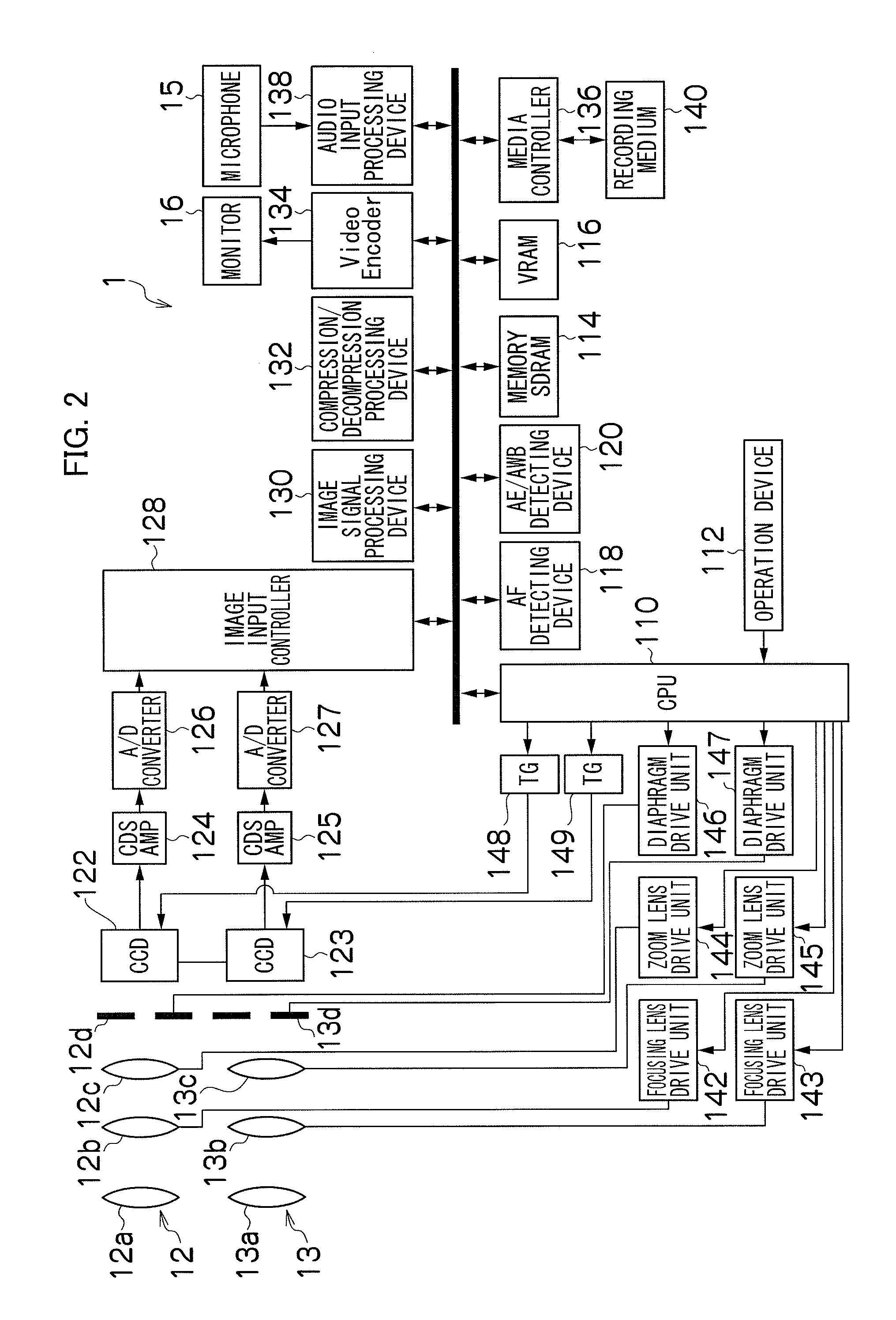
A compound-eye image pickup apparatus includes: a plurality of image pickup devices each including a focusing lens; a moving device configured to move the focusing lens; an automatic focusing device configured to cause the moving device to move the focusing lens within a predetermined range, to acquire focusing positions of each of the plurality of image pickup devices; and a detecting device configured to detect whether or not the focusing position can be acquired, wherein when the detecting device detects that the focusing position of at least one of the plurality of image pickup devices is acquired and the focusing position of the remaining image pickup device is not acquired, the automatic focusing device moves the focusing lens of the image pickup device for which it is detected that the focusing position thereof is not acquired, within an additional range outside of the predetermined range to acquire the focusing position thereof.

Description

BACKGROUND OF THE INVENTION[0001]1. Field of the Invention[0002]The presently disclosed subject matter relates to a compound-eye image pickup apparatus, and more particularly, to a compound-eye image pickup apparatus including a plurality of image pickup devices.[0003]2. Description of the Related Art[0004]Japanese Patent Application Laid-Open No. 07-67023 describes a compound-eye image pickup apparatus including two video cameras, in which a focusing operation is performed on the same subject when optical axes coincide with each other and is performed on the part at which angles of view coincide with each other when the optical axes do not coincide with each other. In addition, the art described in Japanese Patent Application Laid-Open No. 07-67023 describes that, because variations in right and left lens units cause the difference between angles of view, the displacement of an optical axis during zooming, and the deviation of timing in focusing, data for making the angles of view ...

Claims


Application Information

Patent Timeline
IPC IPC(8): H04N5/232
CPCH04N5/2258H04N13/0239H04N5/23212H04N13/239H04N23/45H04N23/673
Inventor KOHAMA, MASAKI
Owner FUJIFILM CORP
Learn More