
Interface apparatus for touch input and tactile output communication

a technology of interface apparatus and input input, applied in the direction of electronic switching, pulse technique, instruments, etc., can solve the problems of not always being able and being unable to see the layout of the switch matrix

Active Publication Date: 2011-03-31
PIXART IMAGING INC
View PDF83 Cites 54 Cited by
  • Summary
  • Abstract
  • Description
  • Claims
  • Application Information

AI Technical Summary

Benefits of technology

[0009]In order to solve the problems associated with conventional touch input technology, the inventive interface apparatus also comprises a tactile output section, which in turn comprises an electro-sensory stimulus generator for generating an electro-sensory stimulus to the body member. The electro-sensory stimulus generator comprises one or more conducting electrodes, each conducting electrode being provided with an insulator wherein, when the body member is proximate to the conducting electrode, the insulator prevents flow of direct current from the conducting electrode to the body member and a capacitive coupling over the insulator is formed between the conducting electrode and the body member. The electro-sensory stimulus generator also comprises a high-voltage source for applying an electrical drive to the one or more conducting electrodes, wherein the electrical drive comprises a first frequency component in a frequency range between 1 Hz and 1000 Hz. The capacitive coupling and electrical drive are dimensioned to produce an electro-sensory sensation, independently of any mechanical vibration of the one or more conducting electrodes or insulators.
[0019]The electro-sensory stimulus generator is preferably dimensioned such that the electrosensory sensation is produced independently of relative motion between the user's body member, such as a finger, and the insulated electrode(s). Creation of the electrosensory sensation without finger movement provides the benefit that the user's finger can feel an underlying area, to which a function is assigned. Some prior art techniques require finger movement to create the electrosensory sensation. For instance, reference document 1 (Yamamoto) discloses a technique in which a variable electric field is used to modulate the frictional force between the finger and the underlying surface. This means that the inventive technique can provide an indication when the user's finger is (stationary) on top of a predefined area, whereas the prior art, as exemplified by Yamamoto, can only indicate when the user's finger is moving over the predefined area. The ability to provide an indication of a stationary finger on top of a predefined area brings about the benefit that the user may select the function assigned to the predefined area, and then let their finger rest in place to wait for an acknowledgment that the user's selection of function has been accepted. The acknowledgment may be provided by varying the electrosensory stimulus, while the user's finger is stationary on top of the predefined area.

Problems solved by technology

A problem with conventional touch screen interfaces is that the user of the touch screen interface must be able to see the layout of the switch matrix in order to be able to select a specific key to be activated (“pushed”).
Seeing the layout of the switch matrix is not always possible or easy, and visually impaired persons are a prime example.
Even in cases wherein the user could see the switch matrix layout, looking at the switch matrix layout may disturb the user, such as the driver of a car.

Method used


Image

  • Interface apparatus for touch input and tactile output communication
  • Interface apparatus for touch input and tactile output communication
  • Interface apparatus for touch input and tactile output communication

Examples


Embodiment Construction

[0037]The embodiments described in the following relate to the operation and implementation of a capacitive electro-sensory interface (“CEI”) which can be employed in the inventive touch screen interface.

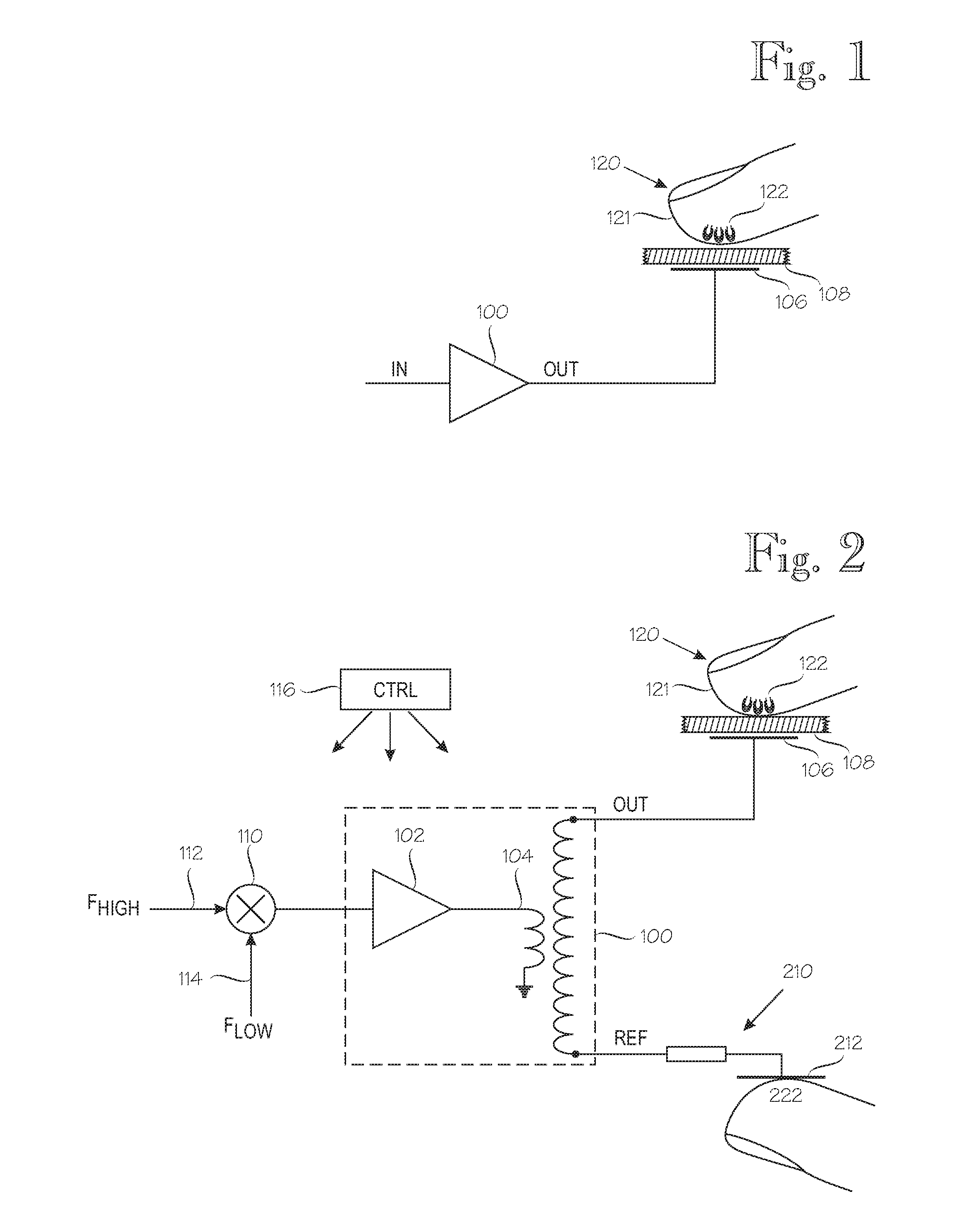
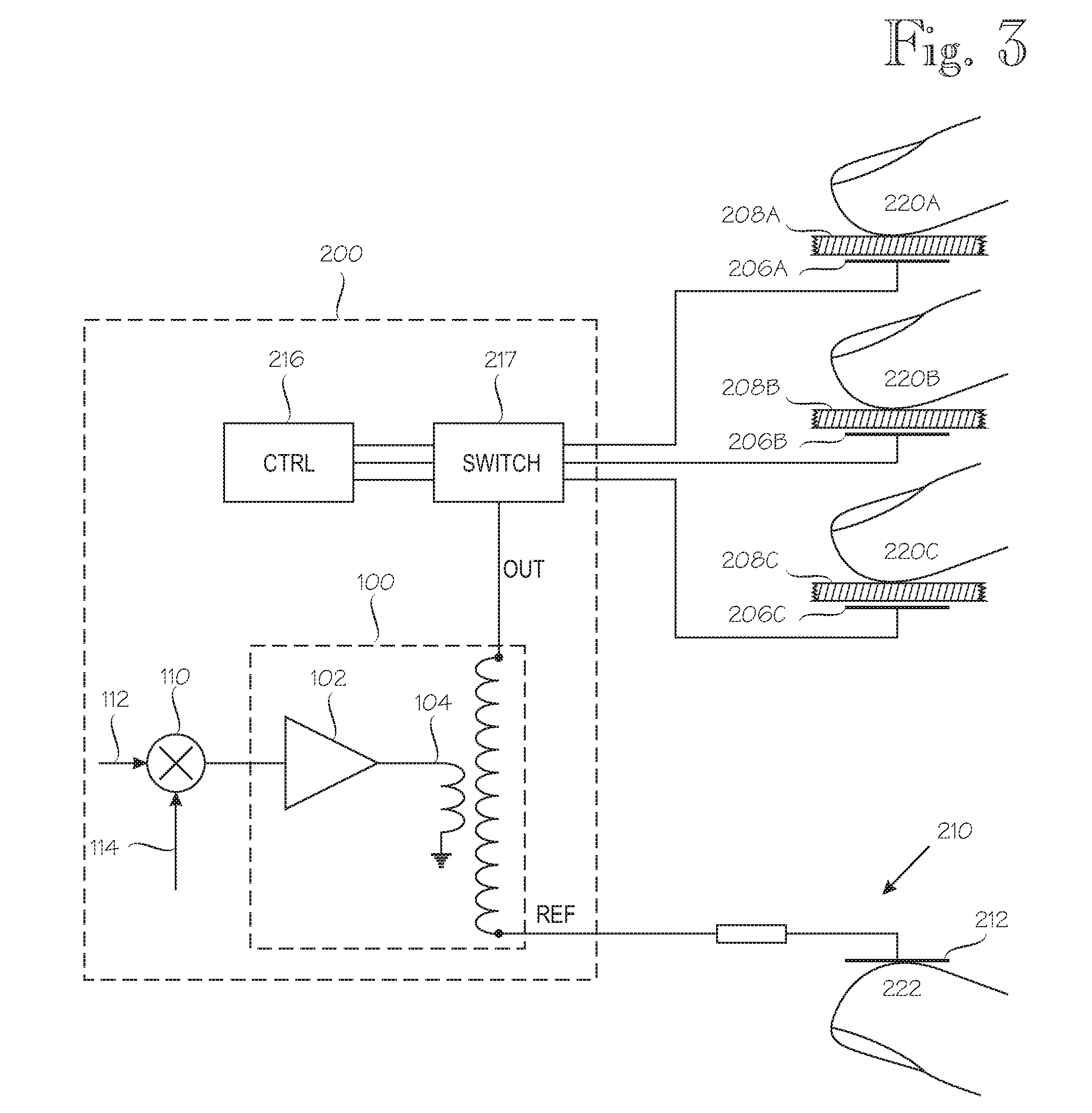
[0038]FIG. 1 illustrates the operating principle of the CEI. Reference numeral 100 denotes a high-voltage amplifier. The output of the high-voltage amplifier 100, denoted OUT, is coupled to an electrode 106 which is insulated against galvanic contact by an insulator 108 which comprises at least one insulation layer or member. Reference numeral 120 generally denotes a body member to be stimulated, such as a human finger. Human skin, which is denoted by reference numeral 121, is a relatively good insulator when dry, but the CEI provides a relatively good capacitive coupling between the electrode 106 and the body member 120. The capacitive coupling is virtually independent from skin conditions, such as moisture. The inventors' hypothesis is that the capacitive coupling between the elec...


PUM


Abstract

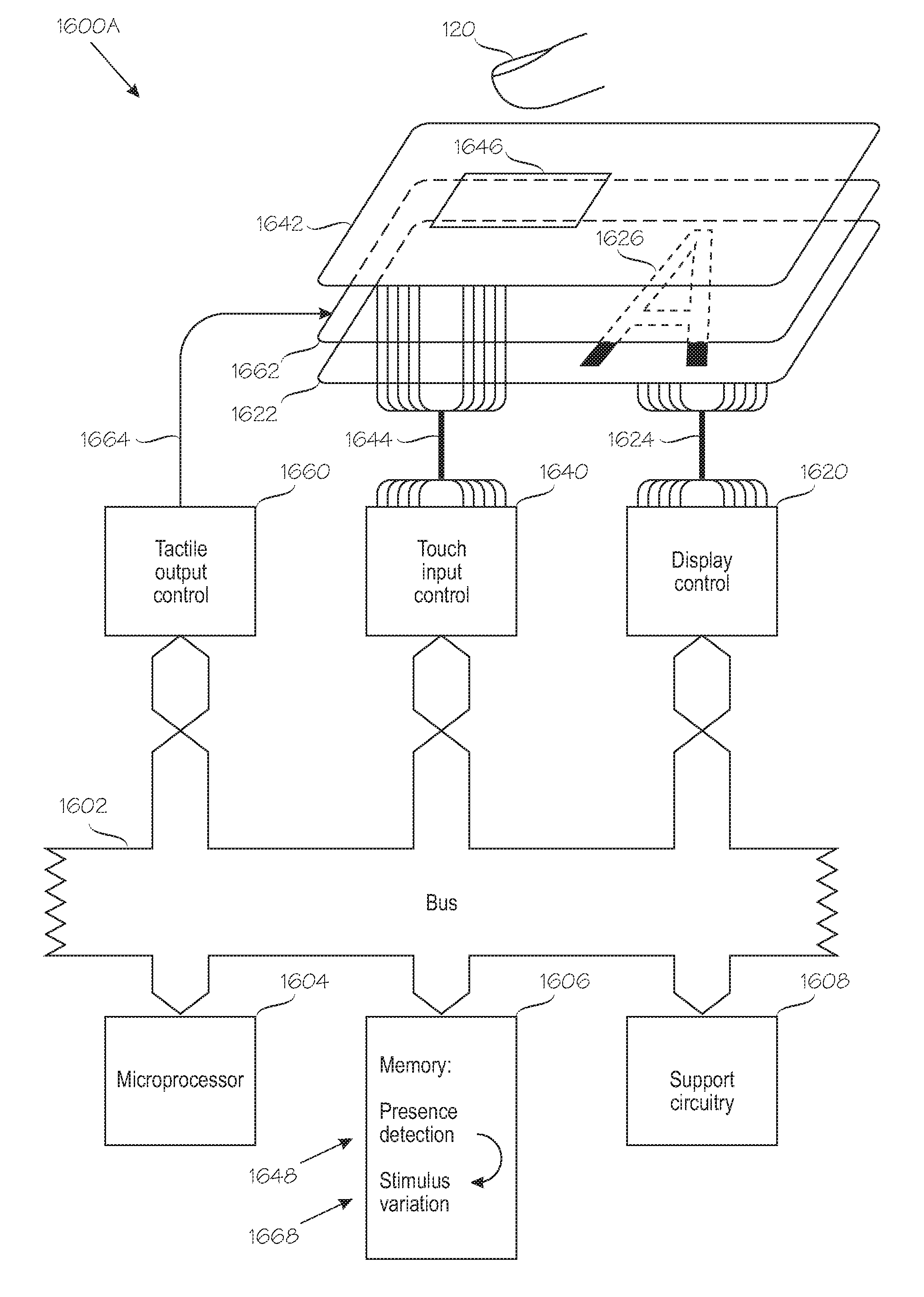
An interface apparatus (1600A) comprises a surface (1642) touchable by a finger (120). The surface has a touch-sensitive area with a predetermined position (1646), to which a function is assigned. The finger's presence at the predetermined position (1646) is detected. An electrosensory stimulus is generated to the finger by applying an alternating electrical drive to one or more electrodes (1662). Each electrode is provided with an insulator, which prevents DC flow from the electrode to the finger and a capacitive coupling over the insulator is formed between the electrode (1662) and the finger (120). The capacitive coupling and electrical drive are dimensioned to produce an electrosensory sensation, independently of mechanical vibration of the electrode. The electrosensory stimulus is varied temporally based on the detected presence or absence of the of the finger (120) near the at least one touch-sensitive area having the predetermined position (1646).

Description

BACKGROUND OF THE INVENTION[0001]The invention relates to a touch device interface. By way of example, the inventive touch device interface can be used as a user-input section of a touch screen interface. Although a touch screen appears to be a unitary piece of hardware, it actually comprises an output device, namely a display or screen, and an input device which is sensitive to touching or approaching the surface of the display with a finger or stylus. Touch screens can be implemented by organizing an x-y matrix of infrared rays over the screen, in which case touching the display surface is not necessary. Alternatively the screen can be overlaid by a transparent pressure-sensitive switch matrix which is scanned in substantially similarly to the way electronic keyboard matrices are scanned. The layout of the switch matrix may resemble that of a general-purpose typewriter, or the layout may be dedicated to specific purposes or applications. Touch screen interfaces are frequently used...

Claims


Application Information

Patent Timeline
IPC IPC(8): G06F3/045G06F3/033G06F3/0354
CPCG09B21/004H03K17/962G06F2203/0339G06F3/016G06F3/03547H03K17/9622
Inventor MAKINEN, VILLESUVANTO, PETROLINJAMA, JUKKA
Owner PIXART IMAGING INC
Learn More