
Image displaying device, image displaying method, and program for displaying images

a technology of image displaying and image, applied in the field of image displaying devices, methods and programs, can solve the problems of not being able to accurately select icons, position input devices, and not being applicable, and achieve the effect of increasing operational options and accurate specification

Active Publication Date: 2011-03-31
FUJIFILM CORP
View PDF7 Cites 62 Cited by
  • Summary
  • Abstract
  • Description
  • Claims
  • Application Information

AI Technical Summary

Benefits of technology

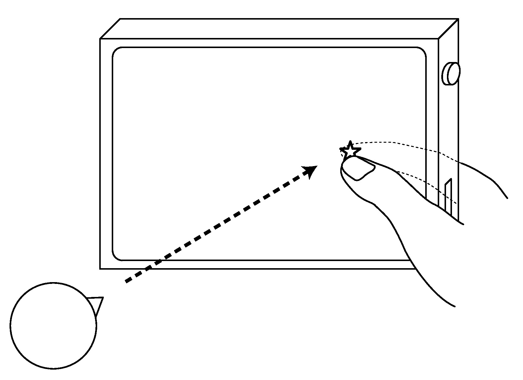
[0008]An object of the present invention is to provide an image displaying device as well as method and program for image manipulation, each making it possible to manipulate displayed image data and so forth without blocking them from view, and accurately specify a focused area of displayed image data and so forth, by mounting touch panels on both the display side (front side) and the back side of the image displaying device and utilizing the characteristics of human digits.
[0010]According to the present invention, displayed image data and so forth can be manipulated without blocking them from view, and a focused area of displayed image data and so forth can accurately be specified. In addition, the manipulation is performed with two digits of one hand which are supporting the image displaying device on its front and back sides, that is to say, the manipulation is readily possible with only one hand. Moreover, the image displaying device of the present invention, as being provided with operation units on its front and back sides, can increase operational options as compared with a device provided with a touch panel only on one side.

Problems solved by technology

In the device as disclosed in JP 11-353115 A, however, the finger operating the flat pad is hidden from the user behind the display unit and, consequently, it is not possible to, for instance, accurately select the icon of the operation of interest from multiple icons displayed on the screen.
In addition, the position input device of JP 11-353115 A is not applicable in the case where an image displayed on a screen is subjected to scaling and so forth around a specified point as the center because, during such image processings, no characters to be inverted are displayed.
In that case, however, the cost of the device is increased, and the finger seen through the display unit also blocks a displayed image and so forth from view.

Method used


Image

  • Image displaying device, image displaying method, and program for displaying images
  • Image displaying device, image displaying method, and program for displaying images
  • Image displaying device, image displaying method, and program for displaying images

Examples


Embodiment Construction

[0032]The image displaying device of the present invention for implementing the image manipulating method according to the present invention will be described below in detail based on the preferred embodiments as shown in the attached drawings.

[0033]First of all, the characteristics of human digits utilized for the image manipulating method according to the present invention are explained. FIG. 1 is a diagram illustrating the characteristics of human digits. As shown in FIG. 1, the thumb and any finger (the index finger, the second finger, the third finger or the little finger) of one and the same hand can easily be joined together without viewing. With such characteristics being utilized, it is readily possible that any finger touches the back side of an image displaying device at the location corresponding in coordinate pair to the location at which the thumb touches the front side with a display unit provided thereon, as shown in FIG. 2. In other words, by touching the front side...


PUM


Abstract

Disclosed is an image displaying device including a first touch panel arranged on a display screen and generating first coordinate information representing a first coordinate pair denoting the location of a touch on the panel surface; a second touch panel arranged at the rear of the display screen and generating second coordinate information representing a second coordinate pair denoting the location of a touch on the panel surface; and a control unit detecting concurrent touches on the surfaces of the first and second touch panels and, if the concurrent touches are detected, detecting coordinate pairs overlapping between the first coordinate pairs and the second coordinate pairs to determine whether or not the overlapping coordinate pairs exist in a number not lower than specified. A method of and a program for displaying an image on such an image displaying device are also disclosed.

Description

BACKGROUND OF THE INVENTION[0001]The present invention relates to image displaying devices, methods and programs for manipulating a displayed image or operation screen by means of a touch panel.[0002]During the playback of static image data or video data on a conventional terminal (e.g., a portable audio player having an image playback function, a cellular phone, a digital photo frame, a digital camera, or a digital video camera) provided with a touch panel, such operations as image selection, start and pause of playback, or scaling and rotation of images may be instructed by means of the touch panel provided on a screen.[0003]In that case, instructions are to be given with a user's finger acting on the screen having a played-back image and so forth displayed thereon, and an acting finger will block the image and so forth from view. This causes a problem if an image is scaled up by designating a point in the image as the center of enlargement, for instance, in that an expected point...

Claims


Application Information

Patent Timeline
IPC IPC(8): G06F3/041G06F3/0482G06F3/0488
CPCG06F1/1626G06F1/1684G06F2203/04806G06F3/04883G06F3/0481
Inventor ONO, RYO
Owner FUJIFILM CORP
Learn More