
Manual Instrumented Medical Tool System

a medical tool system and manual technology, applied in the field of manual tools, can solve problems such as the destruction of tumor cells

Inactive Publication Date: 2011-03-24
ENG SERVICES INC
View PDF19 Cites 41 Cited by
  • Summary
  • Abstract
  • Description
  • Claims
  • Application Information

AI Technical Summary

Benefits of technology

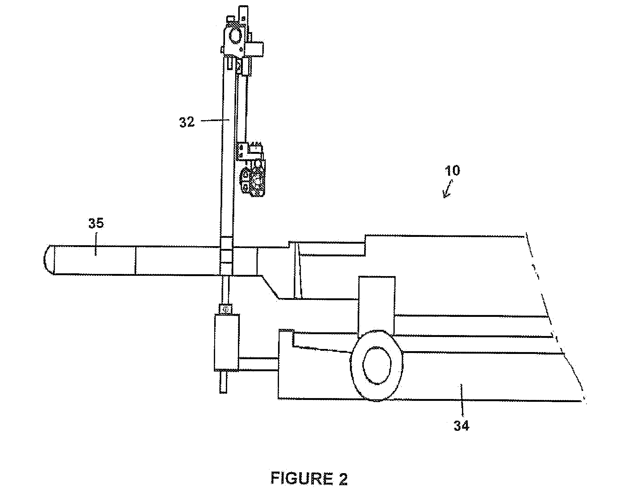
[0006]The present invention relates to a medical device for use in association with a medical image of the gland or organ having a known reference point, the medical device comprising: a structural frame being positioned at a predetermined (and measurable) location relative to the medical image reference point; a horizontal joint operably connected to a horizontal position sensor and operably connected to the frame; a vertical joint operably connected to a vertical position sensor and operably connected to the frame; a pan joint operably connected to a pan position sensor and operably connected to the frame; a tilt joint operably connected a tilt position sensor and operably connected to the frame; a medical instrument assembly operably connected to a medical instrument position sensor and operably connected to the horizontal joint, the vertical joint, the pan joint and the tilt joint; a control system operably connected to the horizontal position sensor, the vertical position sensor, the pan position sensor, the tilt position sensor, the tilt position sensor and the medical instrument position sensor whereby the control system determines the position of a predetermined location on the medical instrument assembly relative to the structural frame.

Problems solved by technology

Implantation of radioactive implants directly into tumors results also in the destruction of the tumor cells.
One particular challenge with these types of surgeries is for the surgeon, during surgery, to know the location of the end of the interventional (surgical) needle with respect to the tumor, that is, the location of the element that comes into contact with the tumor, and provides the anatomical changes thereof.

Method used


Image

  • Manual Instrumented Medical Tool System
  • Manual Instrumented Medical Tool System
  • Manual Instrumented Medical Tool System

Examples


Embodiment Construction

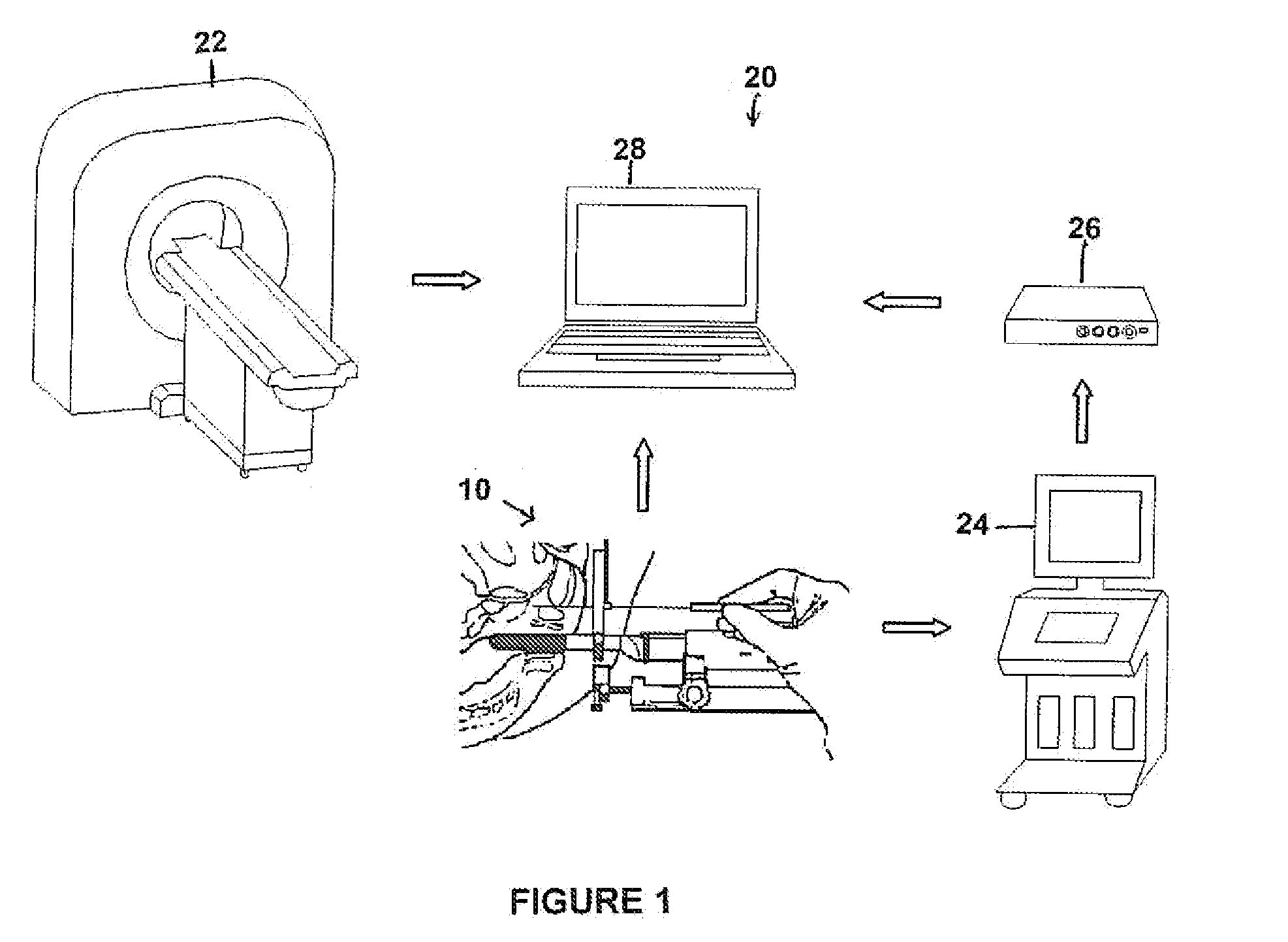
[0052]Referring to FIGS. 1 and 2, the manual instrumented focal ablation tool (MIFAT) of the present invention is adapted to be used in association with a TRUS (trans-rectal ultrasound) device including a probe positioning stepper with the combined MIFAT system shown generally at 10. The MIFAT system is adapted to be used in association with treatment planning and monitoring software system.

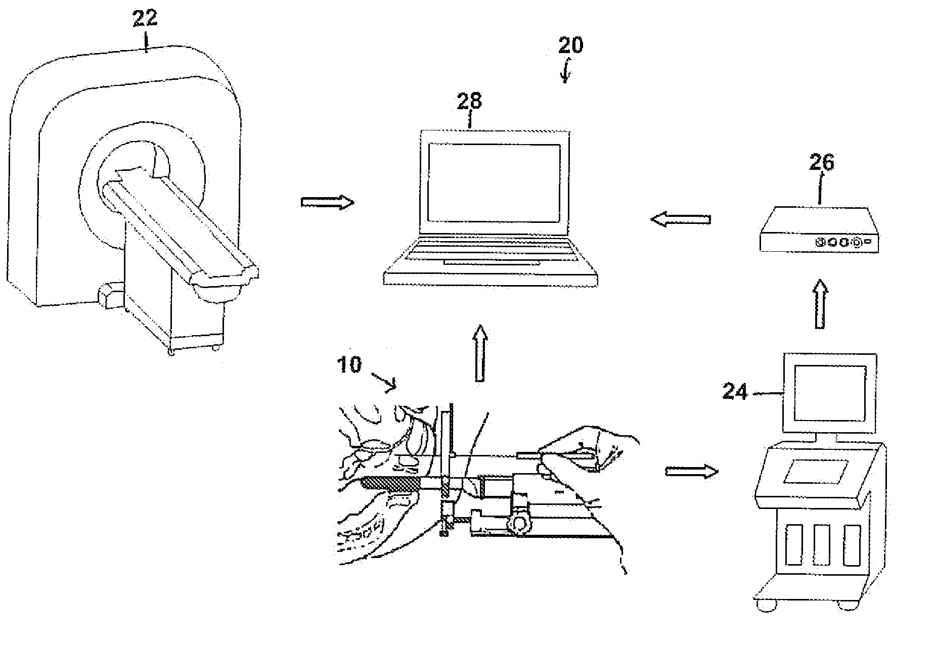
[0053]The MIFAT system architecture is shown in FIG. 1 at 20. The MIFAT system architecture includes the combined MIFAT and stepper with TRUS probe shown at 10, a pre-treatment magnetic resonance imaging 22, real-time ultrasound image 24, video capturer 26 and a computer with a graphical user interface 28.

[0054]The treatment planning and monitoring software system is comprised of the a plurality of modules namely: 1) MRI and ultrasound image-fusion; 2) real-time ultrasound image capture and the contour overlay display; 3) a treatment planning (the best path optimization for the needle insertion);...


PUM


Abstract

A medical device is for use in association with a medical image of the gland or organ having a known reference point. The medical device comprises a structural frame, a horizontal joint, a vertical joint, a pan join, a tilt joint a medical instrument assembly and a control system. The medical device is positioned at a predetermined location relative to the medical image reference point. Each of the horizontal joint, the vertical joint, the pan joint and the tilt joint have a position sensor and are operably connected to the frame. The medical instrument assembly is operably connected to a sensor and to the horizontal joint, the vertical joint, the pan joint and the tilt joint. The control system is operably connected to the other elements whereby the control system determines the position of a predetermined location on the medical instrument assembly relative to the structural frame.

Description

CROSS REFERENCE TO RELATED PATENT APPLICATION[0001]This patent application relates to U.S. Provisional Patent Application Ser. No. 61 / 272,296 filed on Sep. 9, 2009 entitled MANUAL INSTRUMENTED MEDICAL TOOL SYSTEM which is incorporated herein by reference in its entirety.FIELD OF THE INVENTION[0002]This invention relates to tools for use in surgery and in particular manual tools that may be used for Minimally Invasive Surgery (MIS) such as prostate-related interventions: focal ablation, brachytherapy, and biopsyBACKGROUND OF THE INVENTION[0003]The localized treatment of tumors and other medical conditions can be performed by: (i) focal ablation, coagulation of diseased tissue; and (ii) brachytherapy, the implantation of radioactive materials. Focal ablation is used to heat the tissue locally until it coagulates thus destroying the tumor cells. Implantation of radioactive implants directly into tumors results also in the destruction of the tumor cells. These types of surgeries are use...

Claims


Application Information

Patent Timeline
Patent Type & Authority Applications(United States)
IPC IPC(8): A61B5/055A61B6/00
CPCA61B5/055A61B8/0833A61B8/0841A61B8/12A61B8/4209A61B2019/5289A61B19/201A61B2019/5236A61B2019/5259A61B2019/5276A61B8/5238A61B2090/364A61B90/11A61B2090/374A61B2034/2059A61B2090/378A61N5/1007
Inventor GOLDENBERG, ANDREW A.TRACHTENBERG, JOHNYANG, YIMA, LIANG
Owner ENG SERVICES INC
Learn More