
Method, system, and computer-readable medium for improved prediction of spectrum occupancy and estimation of radio signal field strength

Inactive Publication Date: 2011-03-24
CAULFIELD JESSE
View PDF18 Cites 13 Cited by
  • Summary
  • Abstract
  • Description
  • Claims
  • Application Information

AI Technical Summary

Benefits of technology

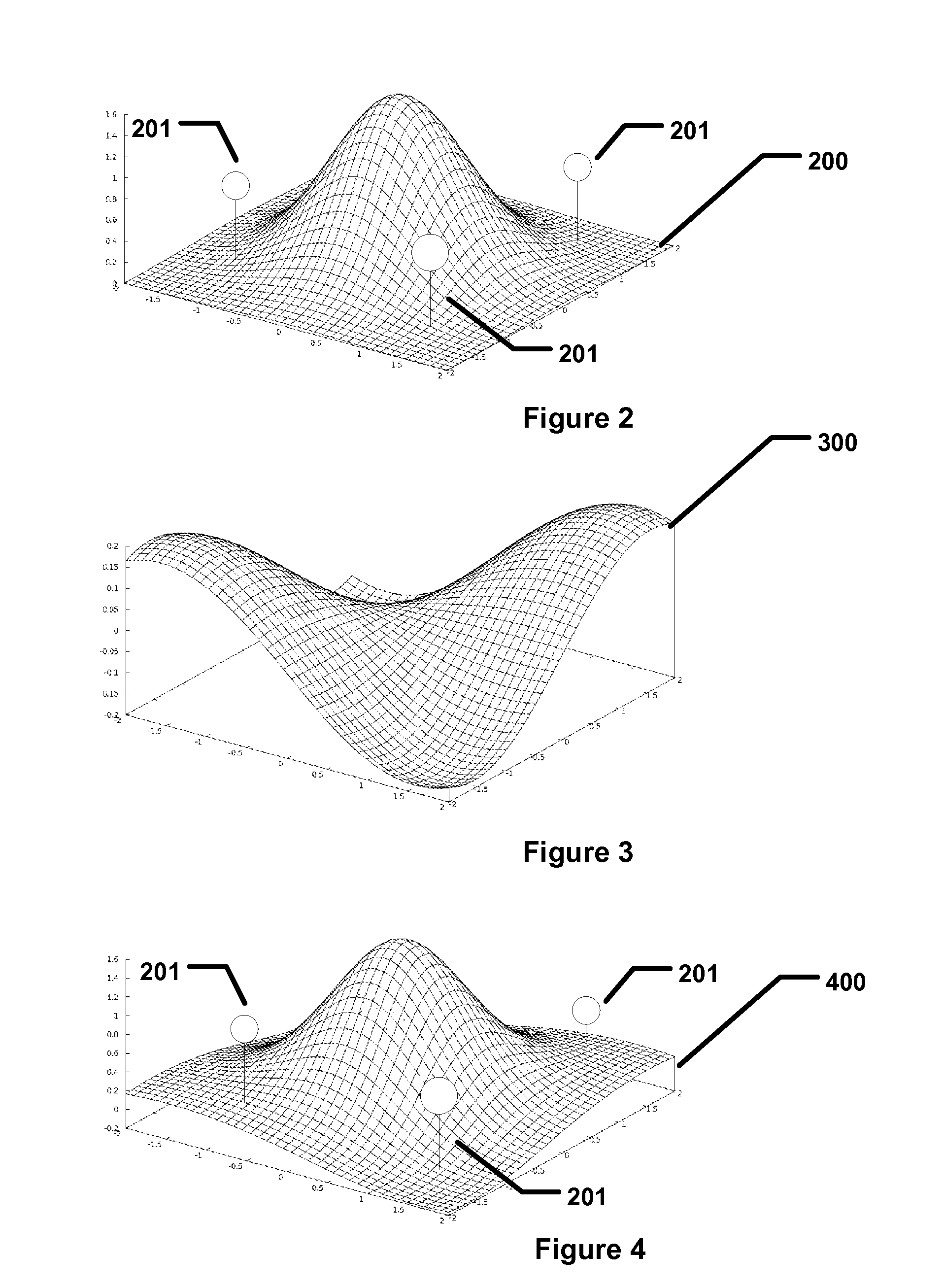
[0007]In an exemplary embodiment, a computer-implemented method to calculate radio propagation and estimate radio signal strength may include calculating a first estimate of radio propagation and signal strength by a computer having at least one processor using a first radio propagation model. The computer-implemented method may also include calculating a second estimate of radio propagation and signal strength by the computer using a second radio propagation model. The computer-implemented method may also include creating a corrective estimate of radio propagation and signal strength by the computer using the first estimate and the second estimate.
[0008]In another embodiment, a system may include a computer which has at least one processor and at least one storage device. The computer may be configured to calculate an estimate of radio propagation and signal strength by using a first radio propagation model

Problems solved by technology

Wireless transmitters such as, but not limited to, AM / FM radio stations, television broadcast stations, mobile phones, medical telemetry devices, wireless microphones, etc. may cause undesired interference with other wireless radiators.
However, protected service contours may not fully contain a transmitter's entire radio signal.
While the spectrum may be unprotected and considered available for operation, this residual signal energy may render the spectrum undesirable or unsuitable for other wireless use.
Relying upon geographic service contours alone may not provide sufficient information for transmitters to effectively avoid interference with other wireless transmitters potentially operating at great distance.

Method used


Image

  • Method, system, and computer-readable medium for improved prediction of spectrum occupancy and estimation of radio signal field strength
  • Method, system, and computer-readable medium for improved prediction of spectrum occupancy and estimation of radio signal field strength
  • Method, system, and computer-readable medium for improved prediction of spectrum occupancy and estimation of radio signal field strength

Examples


Embodiment Construction

Overview

[0019]One purpose of radio wave propagation models may be to predict the received signal strength at a given distance from a transmitter. Most large-scale propagation models typically predict the mean signal strength between transmitter-receiver pair for a given separation distance while short-scale propagation models, in contrast, are designed to study and predict a received signal's amplitude, phase or multipath interference for local geometries like urban environments or inside buildings.

[0020]U.S. Pat. No. 5,310,737 (1995) and U.S. Pat. No. 5,752,164 (1998) disclose a method of spectrum sharing that relies on detailed propagation modeling of the primary and secondary communication systems and spectrum occupancy measurements made by the secondary system. The propagation model's estimated values are verified with channel measurement values. However, as noted by the inventor, neither patent employs measured data as a corrective feedback to the propagation model estimates. T...


PUM


Abstract

In an embodiment of the invention, a system may include a specially configured computer having at least one processor and at least one storage device. The computer may be configured to calculate an estimate of radio propagation and signal strength using a first radio propagation model. The computer may recalculate the estimate of radio propagation and signal strength using one or more additional radio propagation models. The computer may store the recalculated estimate of radio propagation and signal strength in storage.

Description

[0001]This application claims the benefit of U.S. Provisional Application No. 61 / 244,447, filed Sep. 22, 2009. The above referenced application is hereby incorporated by reference in its entirety.BACKGROUND[0002]1. Field of the Invention[0003]Various aspects of the present invention generally relate to wireless communications and, more particularly, to the identification of radio signals over large geographic areas and also at specific locations.[0004]2. Description of the Related Art[0005]Wireless transmitters such as, but not limited to, AM / FM radio stations, television broadcast stations, mobile phones, medical telemetry devices, wireless microphones, etc. may cause undesired interference with other wireless radiators. One method of establishing interference avoidance between transmitters may be to define geographic protected contours, or exclusion zones, around primary licensed transmitters. If other unlicensed or secondary transmitters are physically located within the primary ...

Claims


Application Information

Patent Timeline
IPC IPC(8): H04B17/00
CPCH04B17/318H04B17/3912H04B17/373H04B17/336
Inventor CAULFIELD, JESSE
Owner CAULFIELD JESSE
Learn More