
Gas burner for ovens or grills

a burner and gas technology, applied in the field of gas burners, can solve the problems of affecting the operation of the burner, and requiring multiple attempts by users, and achieve the effect of facilitating maintenance replacemen

Active Publication Date: 2011-03-24
SABAF SPA
View PDF10 Cites 16 Cited by
  • Summary
  • Abstract
  • Description
  • Claims
  • Application Information

AI Technical Summary

Benefits of technology

[0019]Thereby such a solution confers high arrangement flexibility of the ignition spark plug, and eventually of the thermocouple, the burner, inside the cavity of the oven, or grill.
[0022]Conveniently, it is possible to dispose such a diversion duct end coincidentally with the burner ignition hole in proximity of an oven wall, for example in proximity of the wall which the burner is coupled to, so that the ignition spark plug, and eventually the safety thermocouple too, might be held at such an oven wall, in proper holes obtained in the latter, and then could protrude into the oven cavity for a short length only, without the need of utilizing elongated brackets and high insulation of the corresponding wirings.
[0024]It has moreover to be noticed the extreme positioning freedom of the ignition spark plug, and eventually of the thermocouple, into the oven cavity, that the present invention entails, allowing, for example, to constrain the ignition spark plug and the possible burner thermocouple in places easily reachable from the outside of the oven, so that their possible replacement for maintenance will result extremely eased.

Problems solved by technology

Problems inherent in the ignition hole position on the burner body can be detected in the constructive need of arranging the ignition spark plug, and eventually the thermocouple, in proximity thereof, and particularly in providing the intruding installation of such an ignition spark plug, and of such a thermocouple, within the oven cavity, such that it will seem accurately disposed at the ignition hole obtained on the burner body.
Particularly, the latter, generally realized in metallic material, when subjected to heat for long time exposures, will necessarily suffer some deformations, inducing the removal, or anyway the moving, of the ignition spark plug from the reliable position in proximity of the ignition hole.
The deformations of the mounting support, above described, combined with the ignition spark plug overheating, would determine difficulties in possible hot re-ignition of the burner, forcing the user to multiple attempts.
Such wirings must be conveniently insulated, with the consequent realization difficulties, in the length in which these are extending into the oven cavity.

Method used


Image

  • Gas burner for ovens or grills
  • Gas burner for ovens or grills
  • Gas burner for ovens or grills

Examples


Embodiment Construction

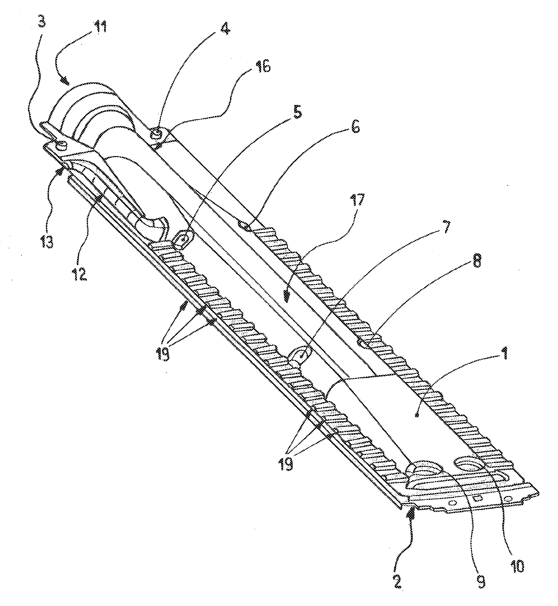
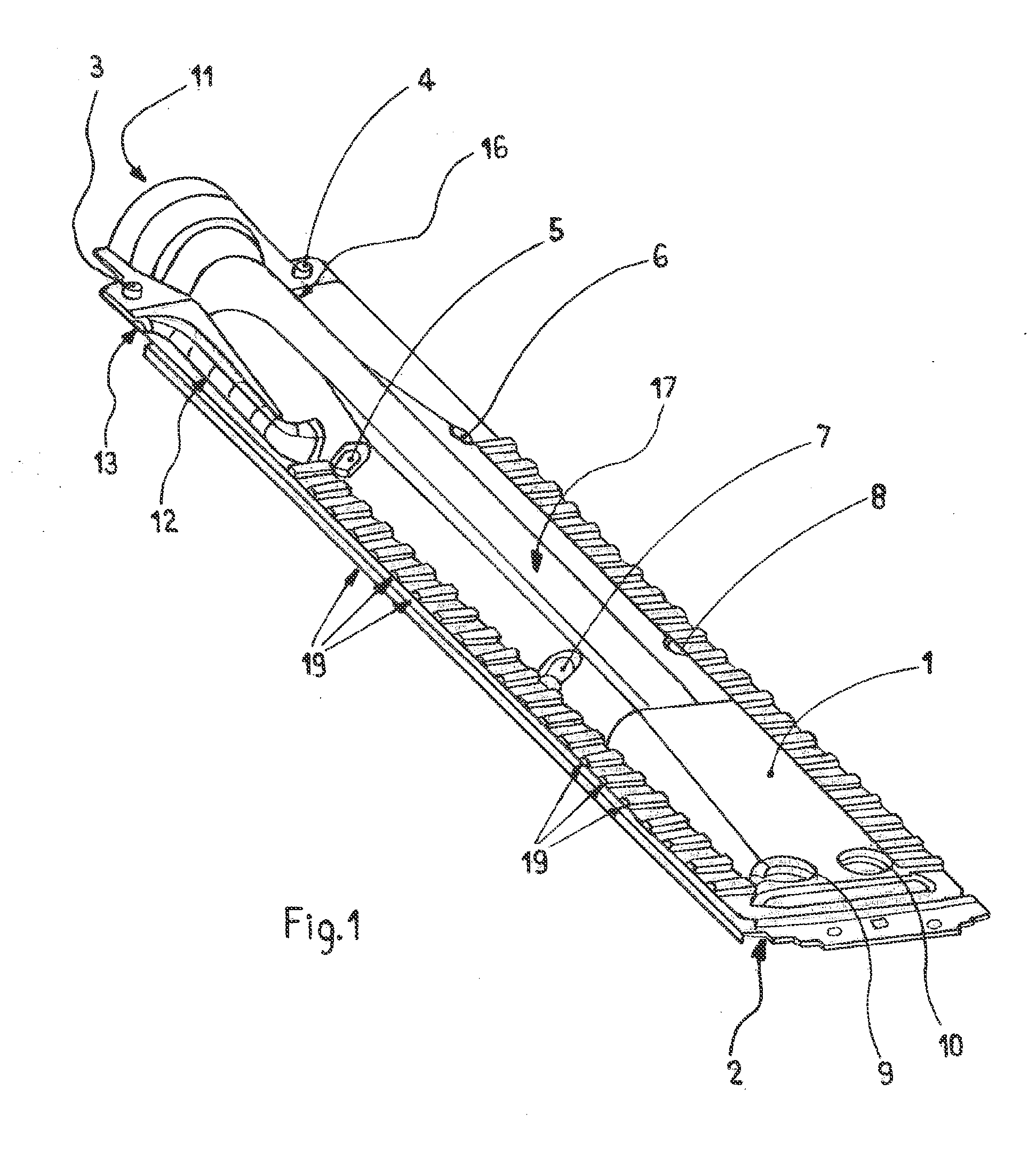
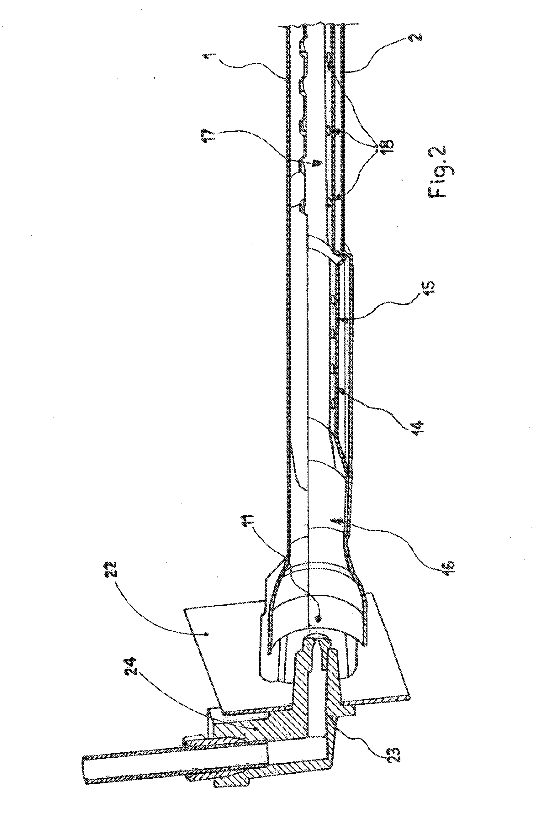
[0031]Firstly referring to FIG. 1, the gas burner object of the present invention, in its preferred embodiment herein explained, comprises an upper metallic semi-shell 1, a lower metallic semi-shell 2, and preferably an intermediate pierced plate 14, all preferably shaped by moulding, such that to define in their inside, once coupled, a Venturi tube 16 for mixing the fuel gas with air (primary air) drawn from the outside of the burner, and at least one elongated chamber 17, coaxial to the Venturi tube 16, for distributing the fuel mixture of gas-primary air to a plurality of flame openings 19, directly realized along the side walls of the elongated chamber 17, or anyway fluidically connected to such a distribution chamber 17.

[0032]The two semi-shells 1, 2 might be mutually coupled, preferably, as will be mentioned, with the interposition of a pierced plate 14, by known clamping elements 3, 4, 5, 6, 7, 8, 9, 10, for example of the screw and nut screw type, situated in various places ...


PUM


Abstract

Gas burner for oven, or grill, of the type comprising at least one Venturi tube (16), for forming the fuel mixture of primary air-gas, having at least one zone with a reduced section followed by a zone with a diverging section, at least one distribution chamber (17) of the fuel mixture, placed downstream the zone with a diverging section of the Venturi tube (16), and a plurality of flame openings (19) for the outflow of the fuel mixture, obtained within such a distribution chamber (17), or in fluidic communication with the latter, as well at least one ignition hole (13) for igniting the burner. Advantageously the latter comprises at least one diversion duct (12) for part of the flow of the fuel mixture, exhibiting its own inlet section obtained in a sector downstream the zone with a reduced section of the Venturi tube (16), and its own outlet section placed at the afore said ignition hole (13).

Description

FIELD OF THE INVENTION[0001]The present invention refers to a gas burner of the elongated type, to be used in oven or grill, comprising a mixing chamber, composed of a Venturi tube, adapted to create a mixture of gas-primary air, and an elongated chamber, situated downstream the Venturi tube, provided with a plurality of holes for such a fuel mixture outflow and the corresponding combustion.KNOWN PREVIOUS ART[0002]In this type of burner, the mixture of primary air-fuel gas is first made carrying the inlet gas flow through a mixing chamber, composed of a Venturi tube open to the surrounding air, then it is introduced into an elongated main chamber, and successively it is burnt after its outflow through the holes, or openings, obtained in such an elongated main chamber, and conveniently shaped for the optimal flame generating after such a mixture ignition.[0003]The mixture ignition is commonly controlled by the user by means of an proper device comprising an ignition spark plug electr...

Claims


Application Information

Patent Timeline
IPC IPC(8): F24C3/08F24C3/10
CPCF23Q9/045F23D14/105F23D2207/00F24C3/10F23D2208/10F23D14/085F23D14/10
Inventor BETTINZOLI, ANGELO
Owner SABAF SPA
Learn More