
System and Method for Supporting Antenna Beamforming in a Cellular Network

Active Publication Date: 2011-03-17
APPLE INC
View PDF19 Cites 171 Cited by
  • Summary
  • Abstract
  • Description
  • Claims
  • Application Information

AI Technical Summary

Benefits of technology

[0015]The pilot channel signaling design improves network bandwidth performance and improves the tracking of user channel characteristics, mobility, and location. Feedback and reporting rules can be established using a particular field designator, CQI, in the preferred embodiment. Further, a control signaling design is proposed in the present invention to improve network bandwidth performance and improve the tracking of user channel characteristics, mobility, and location, which uses the forward link (downlink) control signal, FL, in the preferred embodiment. These pilot channel and control signaling designs assist the system in analyzing which directional transmission beam is best suited for the transmission to the user equipment or when the directional transmission beam should be activated. The present invention solves problems associated with tracking user equipment spatial channel characteristics, mobility or location, improve bandwidth and coverage performance of the network, and reduce overhead transmissions of the network.

Problems solved by technology

The available spectrum for wireless services is limited, however, and the prior attempts to increase traffic within a fixed bandwidth have increased interference in the system and degraded signal quality.
One problem exists when prior art omni-directional antennas are used at the basestation because the transmission / reception of each user's signal becomes a source of interference to other users located in the same cell location on the network, making the overall system interference limited.
This results in wasting power on transmissions when there are no mobile units to reach, in addition to causing interference for adjacent cells using the same frequency, so called co-channel cells.
However, the mobility and spatial channel tracking of the user's location in the network cell required by these beamforming antenna systems increases the overhead of the system.
Moreover, mobility and spatial channel tracking may not be possible or practical with mobile stations moving at relatively high velocities.

Method used


Image

  • System and Method for Supporting Antenna Beamforming in a Cellular Network
  • System and Method for Supporting Antenna Beamforming in a Cellular Network
  • System and Method for Supporting Antenna Beamforming in a Cellular Network

Examples


Embodiment Construction

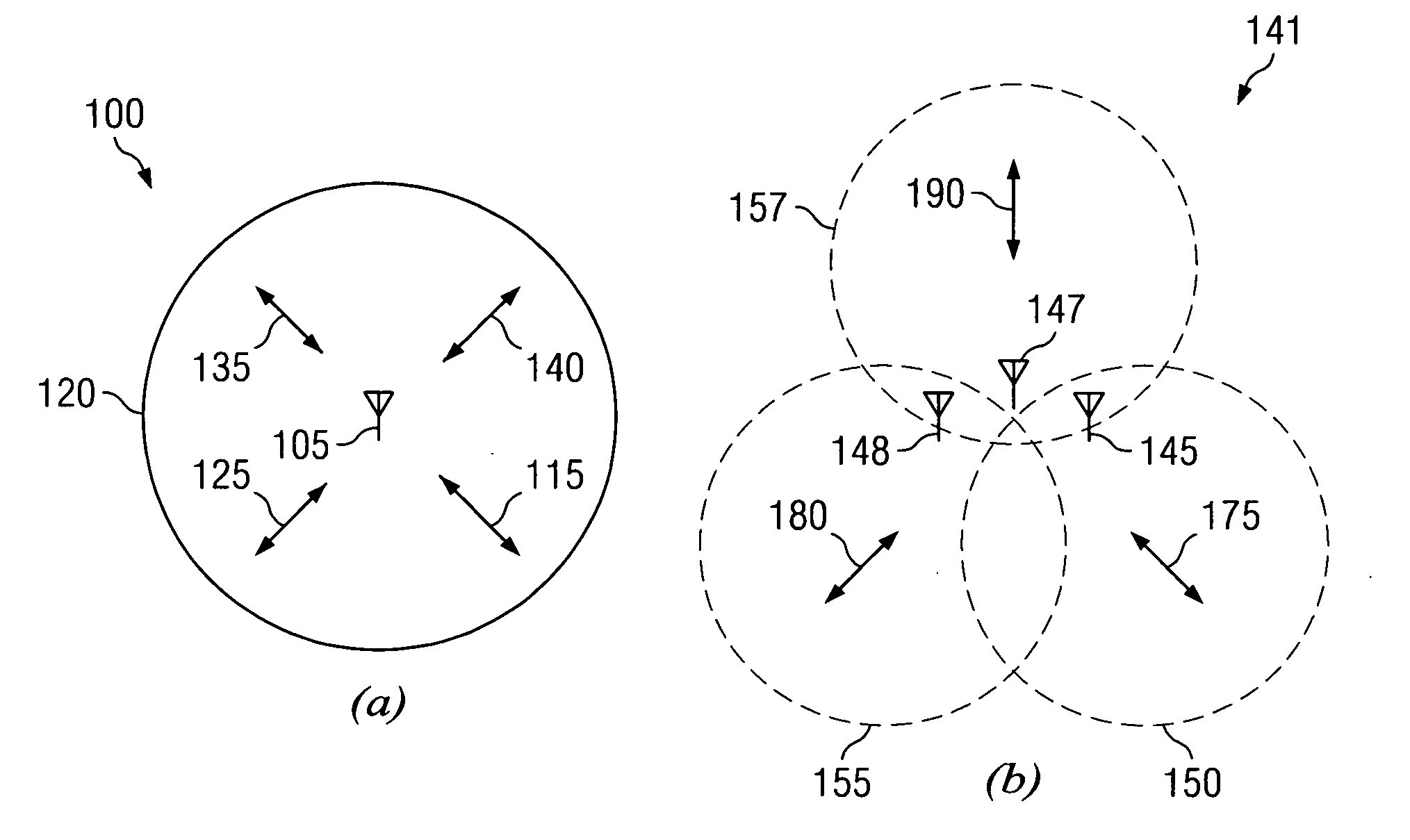
[0032]In FIG. 1(a), the overall transmission architecture 100 of an omni-directional antenna 105 that transmits radially outward equally in various directions shown by arrows 125, 115, 135 and 140. The perimeter of the coverage area is shown by the area 120 for the transmission architecture 100. Improved efficiencies have been achieved by using the sectorized antenna architecture 141 shown in FIG. 1(b).

[0033]Multiple antennas 145, 147 and 148 are shown in the architecture 140, wherein each antenna is directed toward a different region of the cellular network shown by the directional transmission 175 for coverage area 150, transmission 190 for coverage area 157, and directional transmission 180 for coverage area 155. In this context, it is possible for system capacity to be improved by the sectorized architecture.

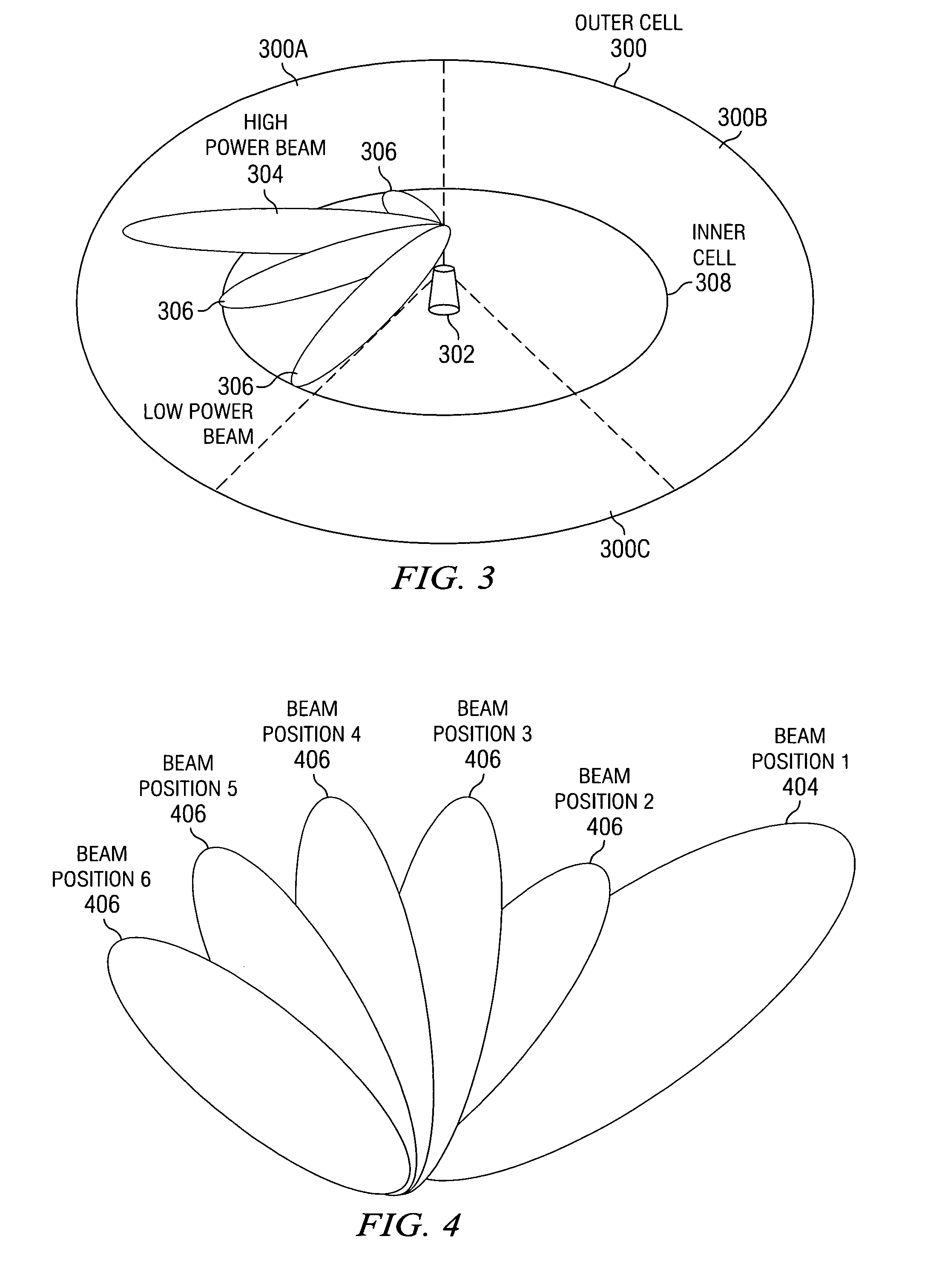
[0034]By varying the strength of various transmission signals, additional efficiencies and reduced interferences can be achieved as shown in FIG. 2 for the sectorized archit...


PUM


Abstract

The present invention is a method and system for supporting a beamfonming antenna system in a mobile broadband communication network with an improved beam pattern, beam sweep pattern, pilot channel design with feedback and reporting rules, and control signaling design. Specifically, the improved beam pattern includes a method of supporting wireless communications in a wireless network forming at least two spatial beams within a cell segment where the at least two spatial beams are associated with different power levels, and separately, where at least two spatial beams can be moved across the cell segment according to a unique sweep pattern. The pilot channel design improves network bandwidth performance and improve user mobility tracking. Feedback and reporting rules can be established using a particular field designator, CQI, in the preferred embodiment.

Description

RELATED APPLICATION DATA[0001]This application is related to Provisional Patent Application Ser. No. 61 / 052,011 filed on May 9, 2008, and priority is claimed for these earlier filing under 35 U.S.C. §119(e), and this application is related to PCT Application Serial No. PCT / US2008 / 078913 filed on Oct. 6, 2008, and priority is claimed for this earlier filing under 35 U.S.C. §120. The Provisional Patent Application and prior PCT Application are incorporated by reference into this utility patent application.TECHNICAL FIELD OF THE INVENTION[0002]The invention relates supporting the formation of spatial beams within a cell segment.BACKGROUND OF THE INVENTION[0003]There is an increasing demand on mobile wireless operators to provide voice and high-speed data services, and at the same time, these operators want to support more users per basestation to reduce overall network costs and make the services affordable to subscribers. As a result, wireless systems that enable higher data rates and...

Claims


Application Information

Patent Timeline
IPC IPC(8): H04W72/08
CPCH04B7/0632H04B7/0695H04L5/0057H04B7/0408H04W52/325H04B7/0617H04B7/0639H04W72/542
Inventor SONG, YITEE, LAI KINGLI, JUN
Owner APPLE INC
Learn More