
Wireless device and signal path configuration method thereof

a wireless device and signal path technology, applied in the direction of transmitter monitoring, receiver monitoring, instruments, etc., can solve the problems of user's hand having a negative influence on the voice and data communication qualities of the wireless device, the antenna radiation characteristics are likely to be degraded, and the internal space available for antenna installation is limited, so as to improve the radiation characteristics of the wireless device

Active Publication Date: 2011-03-17
SAMSUNG ELECTRONICS CO LTD
View PDF20 Cites 34 Cited by
  • Summary
  • Abstract
  • Description
  • Claims
  • Application Information

AI Technical Summary

Benefits of technology

[0009]An aspect of the present invention is to address at least the above-mentioned problems and / or disadvantages and to provide at least the advantages described below. Accordingly, an aspect of the present invention is to provide a signal path configuration method and apparatus of a wireless device that is capable of improving radiation characteristics of the wireless device.
[0010]Also, an aspect of the present invention is to provide a signal path configuration method and apparatus of a wireless device that is capable of improving radiation characteristics of the wireless device by switching a signal path between multiple antennas according to usage environment of the device.
[0011]Another aspect of the present invention is to provide a signal path configuration method and apparatus of a wireless device that is capable of improving radiation characteristics of the wireless device by switching a signal path between multiple antennas according to whether the device is in a communication mode or a Radio Frequency (RF) calibration mode.
[0012]Still another aspect of the present invention is to provide a signal path configuration method and apparatus of a wireless device that is capable of improving radiation characteristics of the wireless device by switching the signal path between multiple antennas designated for respective operation modes, i.e. communication modes and calibration mode, according to the current operation mode.
[0014]Yet another aspect of the present invention is to provide a signal path configuration method and apparatus of a wireless device that is capable of improving radiation characteristics of the wireless device by switching selectively connecting the signal path to one the multiple antennas arranged at upper and lower parts of the wireless device according to a communication mode triggered by an event.
[0015]Still another aspect of the present invention is to provide a signal path configuration method and apparatus of a wireless device that is capable of improving communication service quality and stability by avoiding degradation of the radiation characteristics of antenna in a communication mode and calibrating multiple frequency bands supported by the wireless device collectively without additional process in the calibration mode.

Problems solved by technology

As the wireless devices are becoming slim and compact in design, the available internal space for antenna installation is being limited.
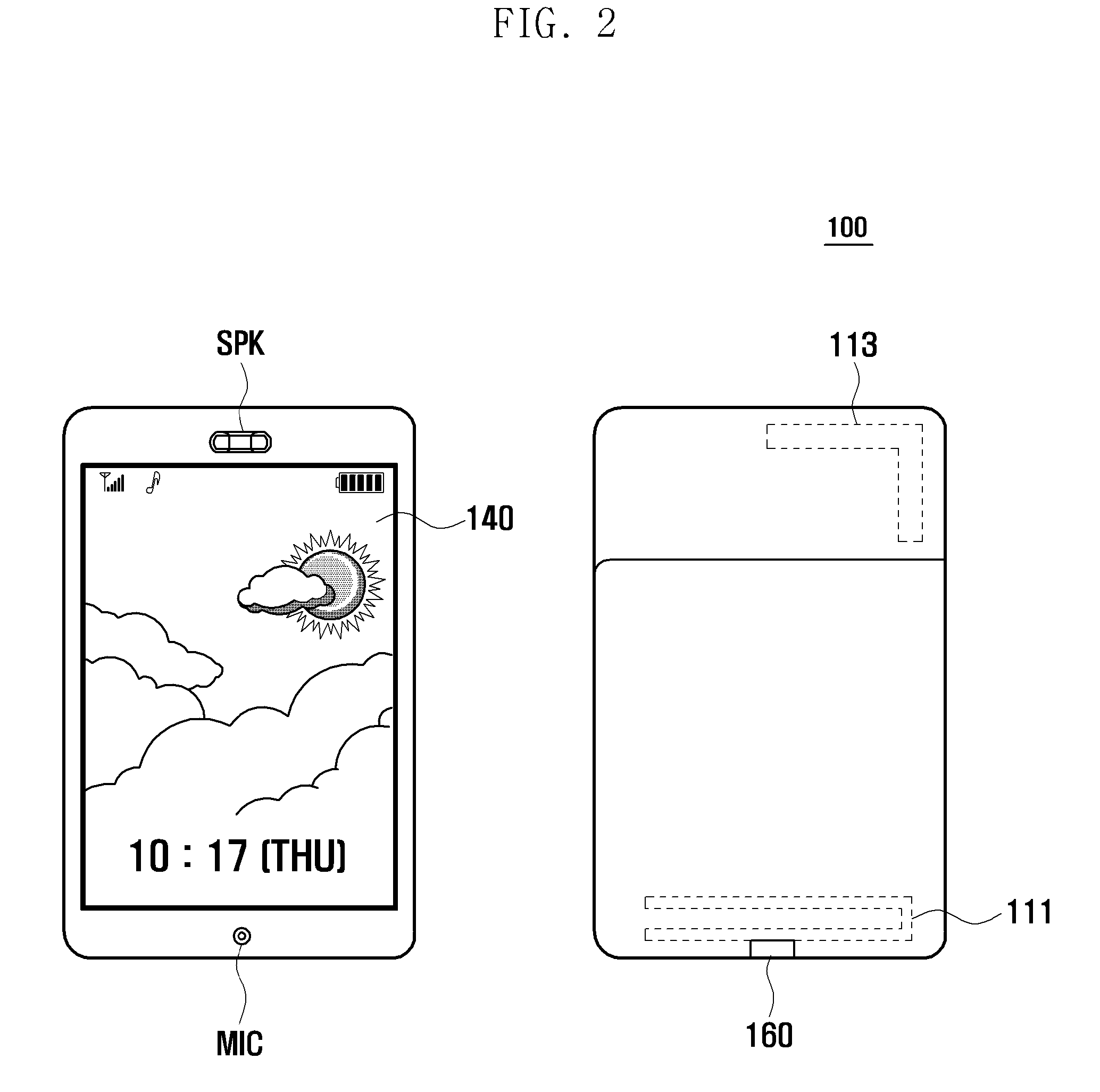
However, since the lower part of the wireless device is held by a user's hand during voice communication, the radiation characteristics of the antenna are likely to be degraded due to the presence of the user's hand.
That is, since it is known that the presence of a hand over an antenna will cause a loss of radiation characteristics of over 6 dB, the presence of the user's hand must negatively influence the voice and data communication qualities of the wireless device.
Accordingly, it is a significant issue to secure the radiation performance of the wireless device in a limited physical structure.
Since the communication service quality is one of the most important factors for determining the device performance, there has been much research conducted to improve communication service quality, and the antenna is one of the main issues related to the communication service quality enhancement.

Method used


Image

  • Wireless device and signal path configuration method thereof
  • Wireless device and signal path configuration method thereof
  • Wireless device and signal path configuration method thereof

Examples


Embodiment Construction

[0028]The following description with reference to the accompanying drawings is provided to assist in a comprehensive understanding of exemplary embodiments of the invention as defined by the claims and their equivalents. It includes various specific details to assist in that understanding but these are to be regarded as merely exemplary. Accordingly, those of ordinary skill in the art will recognize that various changes and modifications of the embodiments described herein can be made without departing from the scope and spirit of the invention. In addition, descriptions of well-known functions and constructions are omitted for clarity and conciseness.

[0029]The terms and words used in the following description and claims are not limited to the bibliographical meanings, but, are merely used by the inventor to enable a clear and consistent understanding of the invention. Accordingly, it should be apparent to those skilled in the art that the following description of exemplary embodime...


PUM


Abstract

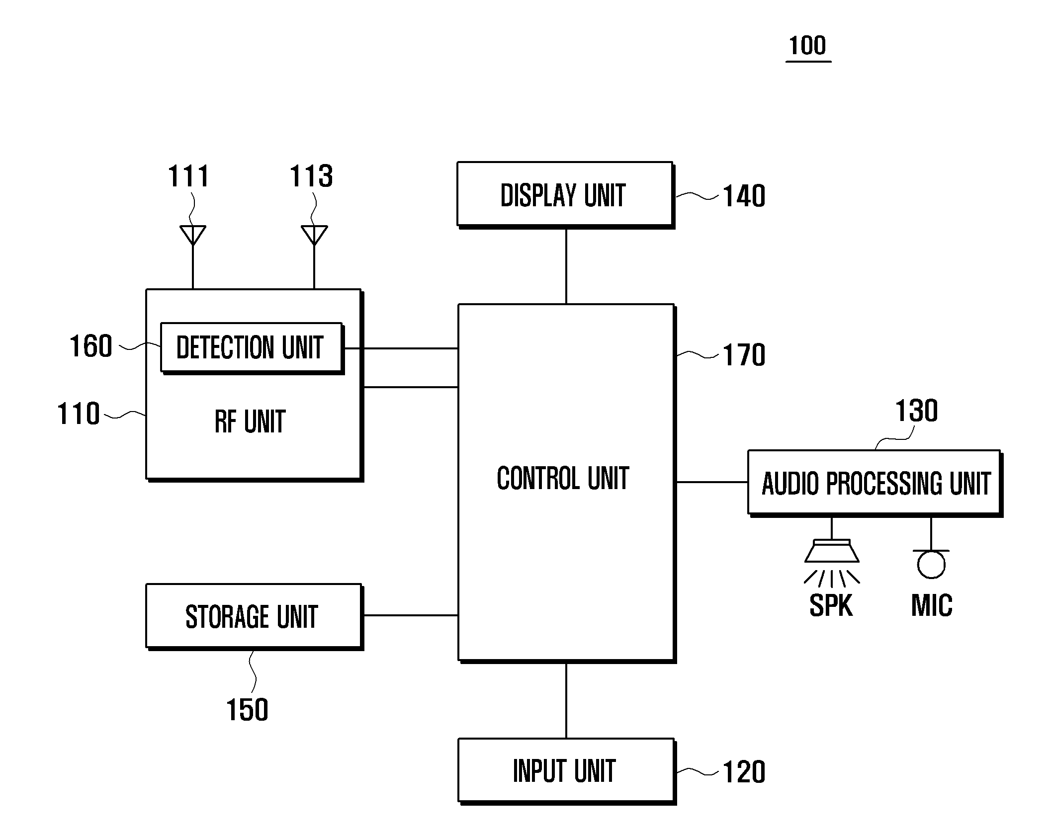
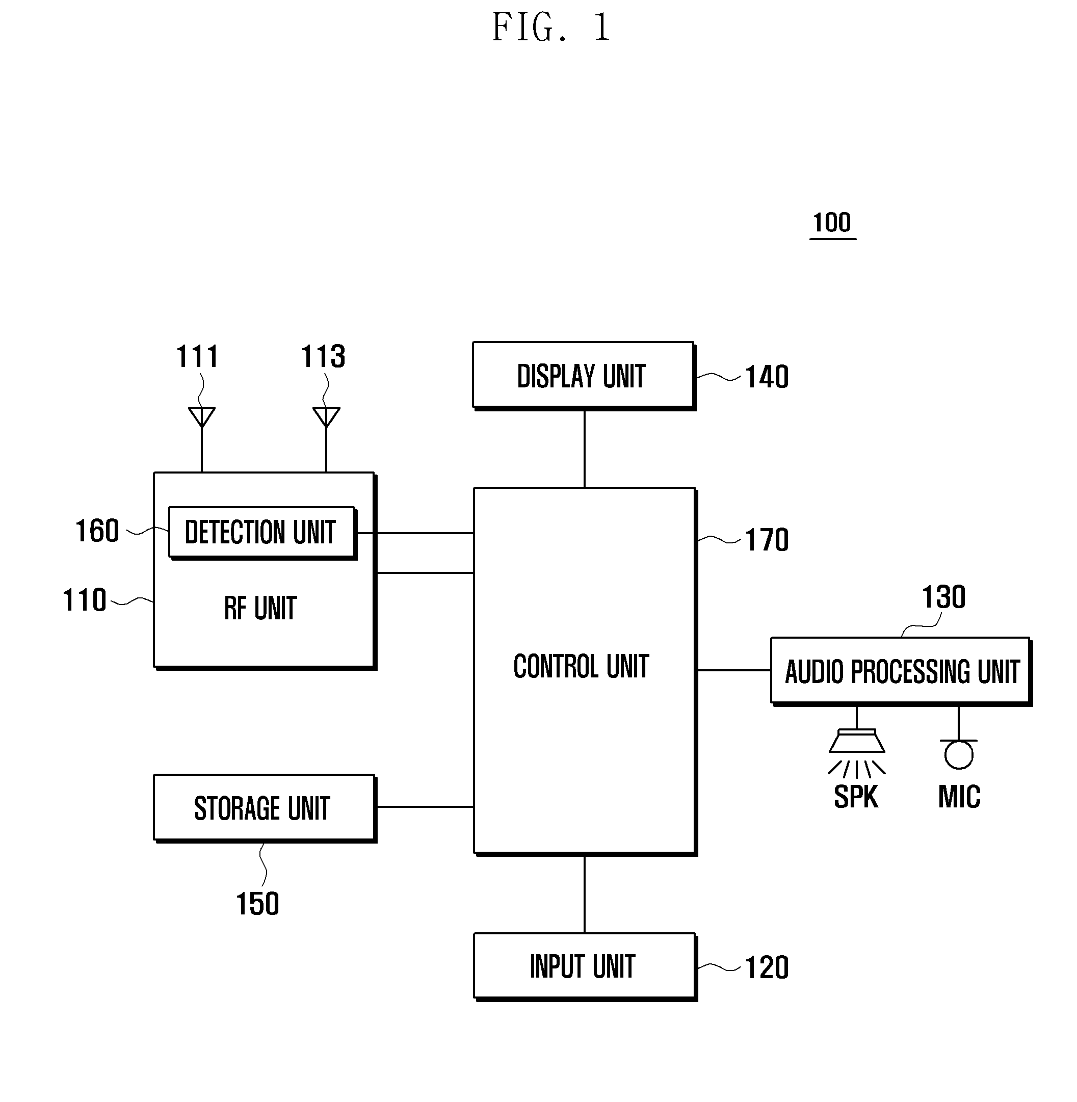
A signal path configuration method and apparatus of a wireless device are provided for avoiding radiation performance degradation caused by holding a specific part of the wireless device. A wireless device of the present invention includes a Radio Frequency (RF) unit that includes a plurality of antennas, an RF connector for RF calibration, and a detection unit for detecting connection of an RF cable, a switch for switching a signal path to one of the plurality of antennas, and a control unit for distinguishing between communication modes based on a detection signal output by the detection unit and for generating a control signal for controlling the switch to connect the signal path to one of the antennas according to the communication mode.

Description

PRIORITY[0001]This application claims the benefit under 35 U.S.C. §119(a) of a Korean patent application filed on Sep. 16, 2009 in the Korean Intellectual Property Office and assigned Serial No. 10-2009-0087572, the entire disclosure of which is hereby incorporated by reference.BACKGROUND OF THE INVENTION[0002]1. Field of the Invention[0003]The present invention relates to a wireless device. More particularly, the present invention relates to a signal path configuration method and apparatus of a wireless device for avoiding radiation performance degradation caused by holding the wireless device.[0004]2. Description of the Related Art[0005]Recent wireless devices are designed with multiband functionality for supporting automatic roaming. Also, most of the recent wireless devices are equipped with internal antennas (so called, intenna) unlike the conventional wireless devices having external antennas.[0006]As the wireless devices are becoming slim and compact in design, the available ...

Claims


Application Information

Patent Timeline
Patent Type & Authority Applications(United States)
IPC IPC(8): H04B17/00
CPCH04B17/21H04B7/0805H04B1/50H04W88/06
Inventor CHUNG, CHANG GWONSHIN, HYUN SEOK
Owner SAMSUNG ELECTRONICS CO LTD
Learn More