
Molding Apparatus for Modified Sulfur Concrete Substance Product

a technology of modified sulfur and concrete, which is applied in the direction of applications, manufacturing tools, sustainable waste treatment, etc., can solve the problems of not having a dedicated mold for filling, cooling, and solidifying sulfur-containing materials, and difficulty in construction,

Inactive Publication Date: 2011-03-17
NIPPON OIL CORP +1
View PDF22 Cites 4 Cited by
  • Summary
  • Abstract
  • Description
  • Claims
  • Application Information

AI Technical Summary

Benefits of technology

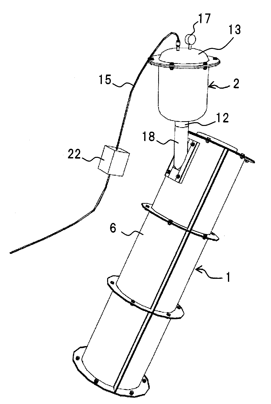
[0012]With such configuration, as the sulfur-containing material fully filled into the cavity of the mold body in which the inside of the outer mold having the cavity which can be hermetically sealed is heated to a temperature within the preset temperature range of which a lower limit is equal to or above a melting point of sulfur, is cooled and contracted in the cavity, the sulfur-containing material stored in the filling tank in which the cover is attached to the upper end opening thereof, so that the inside of the filling tank can be hermetically sealed, and the inside of the filling tank is pressurized to a predetermined pressure, and also, the inside of the filling tank is heated to a temperature within the preset temperature range, is replenished into the cavity by the pressure in the filling tank. Namely, as the sulfur-containing material is cooled and contracted in the cavity of the mold body, the sulfur-containing material in the contracted amount can be automatically replenished from the filling tank. Accordingly, this does not require excessive time and labor. Further, the strength of the modified sulfur concrete substance product is increased, and also, finishing becomes good to enhance the value of the product.
[0014]Still further, in order to heat the mold body and the filling tank to a temperature within the preset temperature range of which a lower limit is equal to or above a melting point of sulfur, heating means is attached to each of the mold body and the filling tank. The heating means attached to each of the components themselves heats the mold body and the filling tank to a temperature within the preset temperature range of which a lower limit is equal to or above a melting point of sulfur. Thus, the temperature of the mold body and the filling tank can be maintained at a temperature equal to or above a melting point of the sulfur, and the sulfur-containing material in a melted state can be filled from the filling tank into the cavity of the mold body.

Problems solved by technology

It is difficult to perform construction by melting, casting and solidifying the sulfur material on site.
There is not a dedicated mold for filling, cooling, and solidifying the sulfur-containing material.
However, a means for heating the outer mold and the inner mold is not provided in the molds described.
Conventionally, when the sulfur-containing material in a melted state solidifies, a part which is in contact with the mold when the material is poured into the mold is cooled rapidly, so that a problem occurs such that the surface of the sulfur concrete substance or the modified sulfur concrete substance removed from the mold is rough.
Thus, even when the sulfur-containing material is fully filled to the upper surface portion of the mold, it is sunk, thereby causing a gap in the upper portion of the product, so that a specification requirement of the product may not be satisfied.
In this case, up to now, the sulfur-containing material is coated onto the product taken out by dividing the mold into two parts for repair, however, this requires excessive time and labor, and also, finishing is poor to deteriorate the value of the product.
Furthermore, when the gap is large, the product may not be repaired.
During that, the surface of the sulfur-containing material starts to solidify to generate a hardened layer, so that the strength of the product is weakened.
In this case, a performance requirement of the product may not be satisfied.

Method used


Image

  • Molding Apparatus for Modified Sulfur Concrete Substance Product
  • Molding Apparatus for Modified Sulfur Concrete Substance Product
  • Molding Apparatus for Modified Sulfur Concrete Substance Product

Examples


Embodiment Construction

[0025]Preferred embodiments of the present invention will be described below in detail with reference to the accompanying drawings.

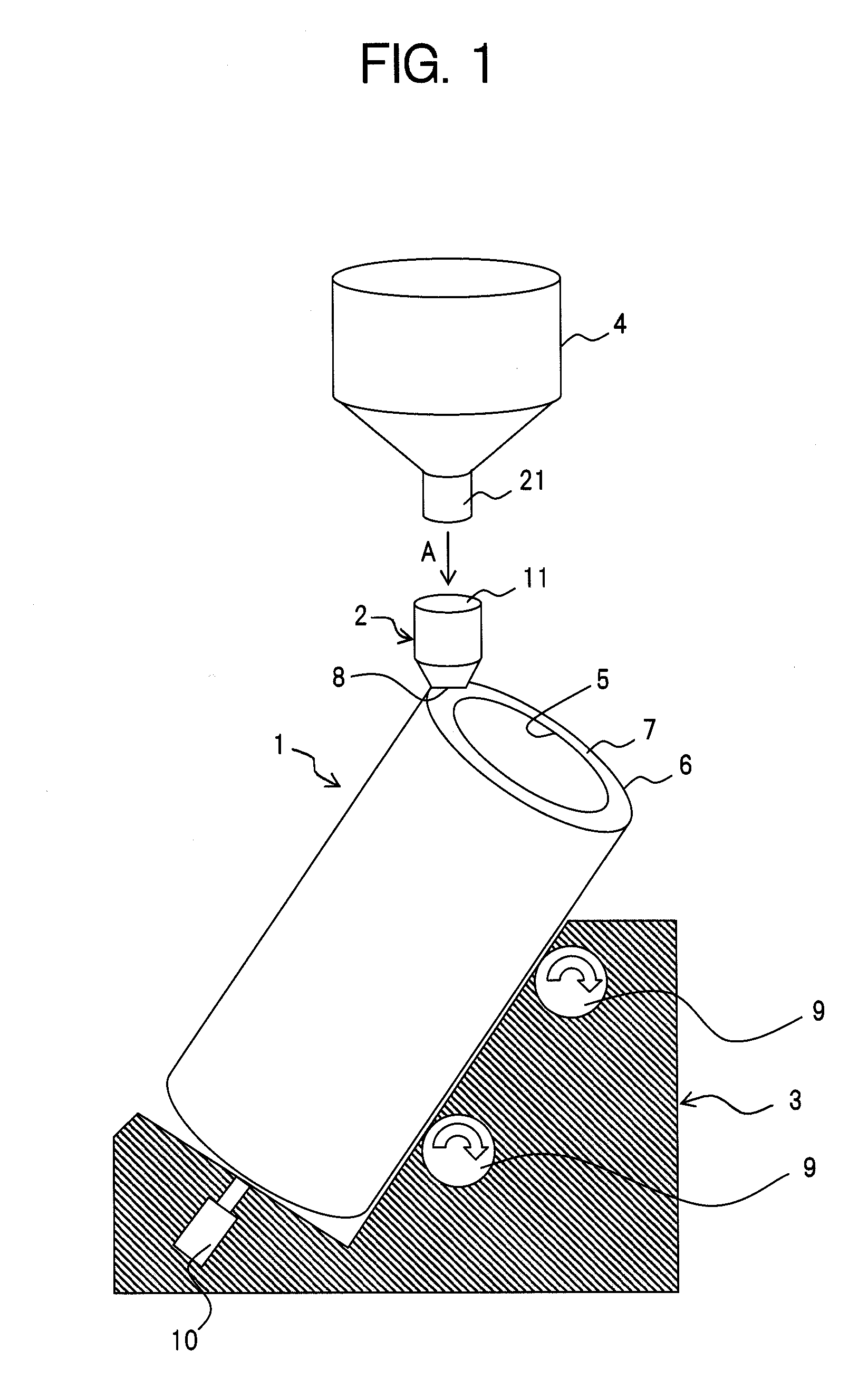
[0026]FIG. 1 is a schematic view illustrating an embodiment of a molding apparatus for modified sulfur concrete substance product according to the present invention.

[0027]The molding apparatus for modified sulfur concrete substance product fills a sulfur-containing material in a melted state into a cavity of a mold body and then cools and solidifies the sulfur-containing material to mold the modified sulfur concrete substance product. As illustrated in FIG. 1, the molding apparatus for modified sulfur concrete substance product has a mold body 1 and a filling tank 2. In FIG. 1, the reference numeral 3 denotes a vibrating table supporting mold body 1 positioned in a tilted state, and the reference numeral 4 denotes an injecting hopper supplying the sulfur-containing material into filling tank 2.

[0028]Mold body 1 fills the sulfur-containing material in a m...


PUM

PropertyMeasurementUnit
temperatureaaaaaaaaaa
melting pointaaaaaaaaaa

Abstract

In the present invention, as a sulfur-containing material fully filled into a cavity of a mold body in which the inside of an outer mold having the cavity which can be hermetically sealed is heated to a temperature within a preset temperature range of which a lower limit is equal to or above a melting point of sulfur is cooled and contracted in the cavity, the sulfur-containing material stored in a filling tank in which a cover is attached to an upper end opening of filling tank, so that the inside of filling tank can be hermetically sealed, and also, the inside of filling tank is pressurized to a predetermined pressure, and the inside of filling tank is heated to a temperature within the preset temperature range, is replenished into the cavity by a pressure in filling tank to mold a modified sulfur concrete substance product.

Description

CROSS-REFERENCE TO RELATED APPLICATIONS[0001]This application is a continuation of international Patent Application PCT / JP2009 / 55785, filed on Mar. 24, 2009, which claims priority to foreign Patent Application JP 2008234316, filed on Sep. 12, 2008, the disclosures of which are incorporated herein by reference in their entirety.FIELD OF THE INVENTION[0002]The present invention relates to a molding apparatus for modified sulfur concrete substance product, which fills a sulfur-containing material in a melted state into a cavity of a mold body and then cools and solidifies the sulfur-containing material to mold the modified sulfur concrete substance product. More specifically, the present invention relates to a molding apparatus for modified sulfur concrete substance product which, as a sulfur-containing material filled into a cavity is cooled and contracted, replenishes the sulfur-containing material in a filling tank in a pressurized state into the cavity.BACKGROUND OF THE INVENTION[0...

Claims


Application Information

Patent Timeline
Patent Type & Authority Applications(United States)
IPC IPC(8): B28B1/24
CPCB28B1/54B28B7/42B28B13/021B28B21/36C04B28/36C04B40/02C04B14/06C04B14/22C04B14/28C04B18/06C04B18/08C04B18/146Y02W30/91
Inventor KURAKAKE, MINORUHORII, HIDEYUKITOMINAGA, YOSHIFUMIYAMAGUCHI, YASUNORI
Owner NIPPON OIL CORP
Learn More