
Imaging system for combined full-color reflectance and near-infrared imaging

a full-color reflectance and near-infrared imaging technology, applied in the field of medical imaging, can solve the problems of limiting image size and/or resolution, increasing the number of image sensors in multi-sensor implementations, and compromising image resolution

Active Publication Date: 2011-03-17
STRYKER EUROPEAN OPERATIONS LIMITED
View PDF33 Cites 177 Cited by
  • Summary
  • Abstract
  • Description
  • Claims
  • Application Information

AI Technical Summary

Benefits of technology

Fields captured by the image sensor and lacking the red light spectral component or the NIR light spectral component may be interpolated from temporally adjacent image fields that include a corresponding red light spectral component or NIR light spectral component. In one embodiment, the NIR light spectral component obtained in the absence of red light may be subtracted from the combined red light / NIR light to obtain the separate red light spectral component. This is advantageous in particular when the detected NIR signal has an intensity comparable to that of the red signal.

Problems solved by technology

Disadvantageously, this increases the number of image sensors in multi-sensor implementations or compromises image resolution when on the same sensor, specific sensor pixels are dedicated for NIR imaging while others are utilized for color imaging.Another conventional configuration utilizes a single monochrome image sensor for sequential imaging of the visible and NIR light.
However, this approach, where image frames are acquired sequentially at different times, can generate objectionable motion artifacts (i.e. color fringing and “rainbow effects”) in the composite color and NIR images.
Because of the high data transfer rate, high frame rates are difficult to implement for high definition images (e.g. 2 million pixels), or images having a large dynamic range (>10 bits), thus limiting image size and / or resolution.

Method used


Image

  • Imaging system for combined full-color reflectance and near-infrared imaging
  • Imaging system for combined full-color reflectance and near-infrared imaging
  • Imaging system for combined full-color reflectance and near-infrared imaging

Examples


Embodiment Construction

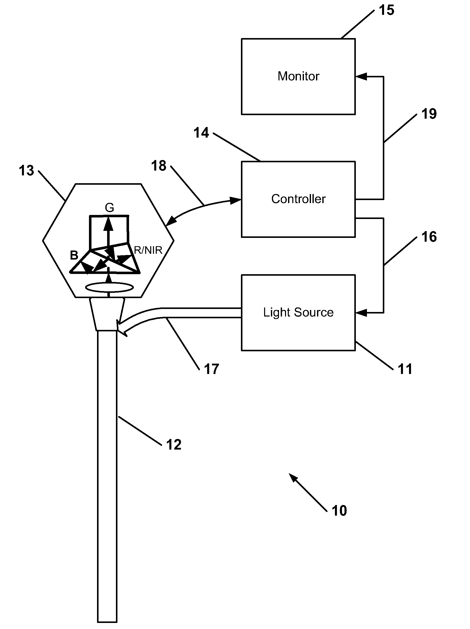
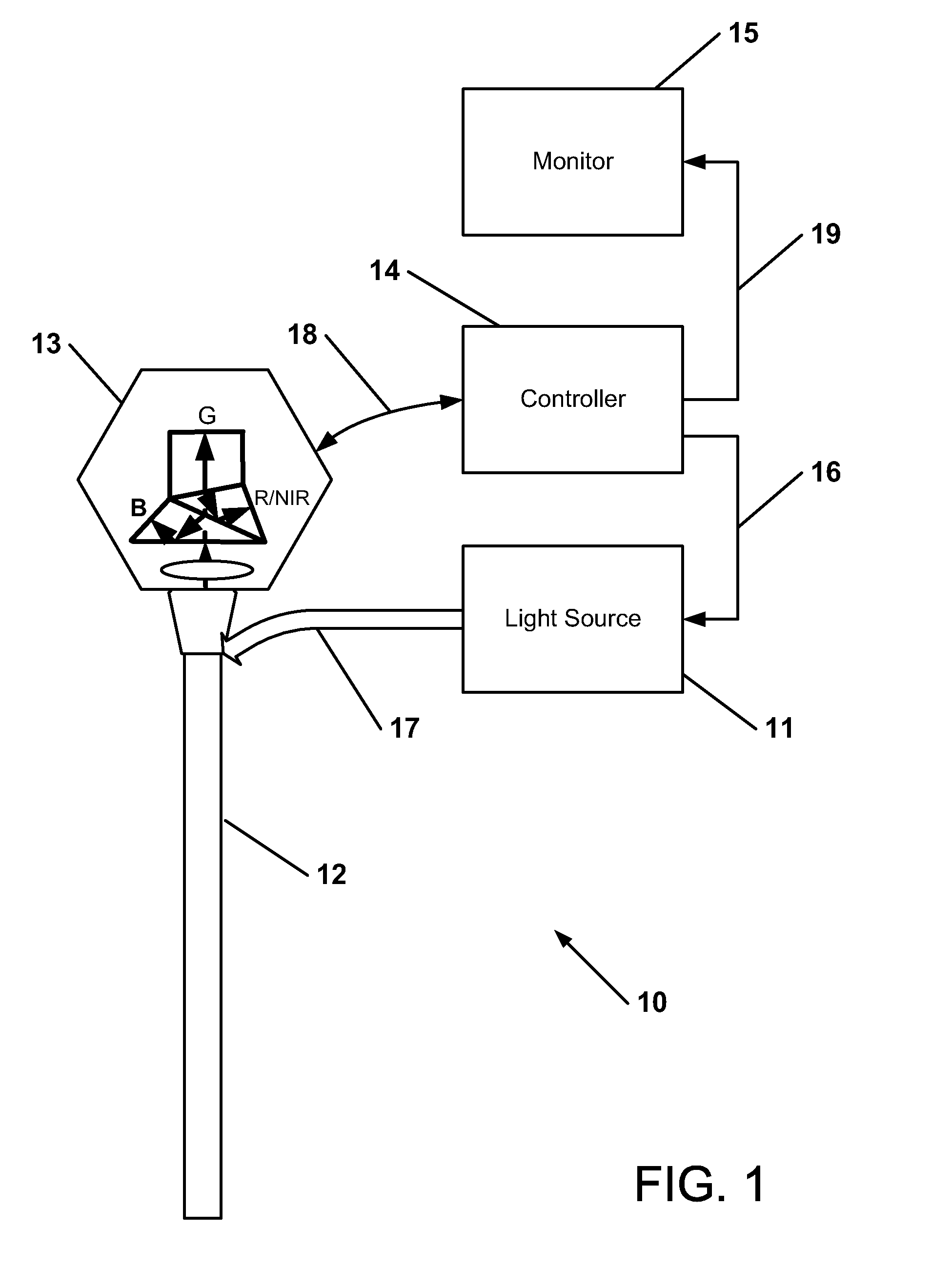
Color video images are generally obtained with three-sensor color cameras where separate red, green and blue image sensors provide simultaneous contiguous arrays of red, green and blue pixel information. Full color video images are generated by combining the image information from all three sensors. Color fidelity (i.e. a true color rendition) is extremely important in medical imaging applications and all three sensors are used to provide complete color information.

To understand the relative importance of color and spatial information in video images of human tissue, however, it is useful to consider information in such video images in terms of luma and chroma. Luma refers to the brightness information in the image and it is this information that provides the spatial detail that enables the viewer to recognize shapes. The spatial and temporal resolution of luma is consequently crucial to the perception of video image quality. Chroma refers to the color information in the video image...


PUM


Abstract

An imaging system for acquisition of NIR and full-color images includes a light source providing visible light and NIR light to an area under observation, such as living tissue, a camera having one or more image sensors configured to separately detect blue reflectance light, green reflectance light, and combined red reflectance light / detected NIR light returned from the area under observation. A controller in signal communication with the light source and the camera is configured to control the light source to continuously illuminate area under observation with temporally continuous blue / green illumination light and with red illumination light and NIR excitation light. At least one of the red illumination light and NIR excitation light are switched on and off periodically in synchronism with the acquisition of red and NIR light images in the camera.

Description

FIELD OF THE INVENTIONThe invention is directed to medical imaging, in particular to a system and method for obtaining visible light images and near infrared light images from an area under observation, such as living tissue, and in particular for use in endoscopy.BACKGROUND OF THE INVENTIONNear-infrared (NIR) imaging has been described in the literature for various clinical applications. Typically such an imaging modality utilizes a contrast agent (e.g. indocyanine green) that absorbs and / or fluoresces in the NIR. Such contrast agents may be conjugated to targeting molecules (e.g. antibodies) for disease detection. The contrast agents may be introduced into tissue intravenously or subcutaneously to image tissue structure and function (e.g. flow of blood / lymph / bile in vessels) that is not easily seen with standard visible light imaging technology.Independently of the clinical application, endoscopic NIR imaging devices typically include multiple imaging modes as a practical feature....

Claims


Application Information

Patent Timeline
IPC IPC(8): H04N5/33H04N7/18
CPCA61B1/00186A61B1/043A61B1/045A61B1/0638A61B5/0062A61B1/0005A61B5/0075A61B5/0086A61B5/418A61B1/0646A61B5/0071A61B1/00009A61B1/00043A61B1/00045A61B1/00163A61B1/04A61B1/042A61B1/06A61B1/0669G06T2207/10048G02B27/1013A61B1/046A61B1/0655H04N23/11H04N23/21H04N5/33A61B5/7425
Inventor FENGLER, JOHNWESTWICK, PAULBAILEY, ARTHUR E.COTTLE, PAUL
Owner STRYKER EUROPEAN OPERATIONS LIMITED
Learn More