Apparatus and Method for Producing Plastic Bottles

Active Publication Date: 2011-03-10
KRONES AG
View PDF17 Cites 24 Cited by
  • Summary
  • Abstract
  • Description
  • Claims
  • Application Information

AI Technical Summary

Benefits of technology

[0006]One aspect of the present disclosure is to develop a generic apparatus in such a way that with a spatially compact and space-saving arrangement the apparatus is nevertheless flexible and easily adaptable to different functions, and to provide a corresponding method therefor.
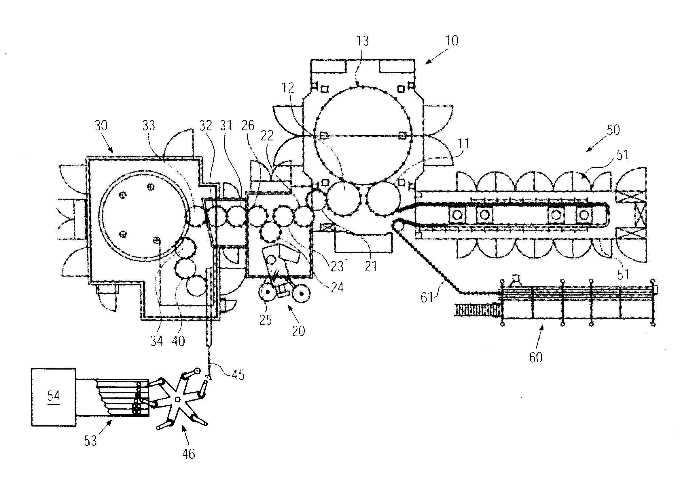
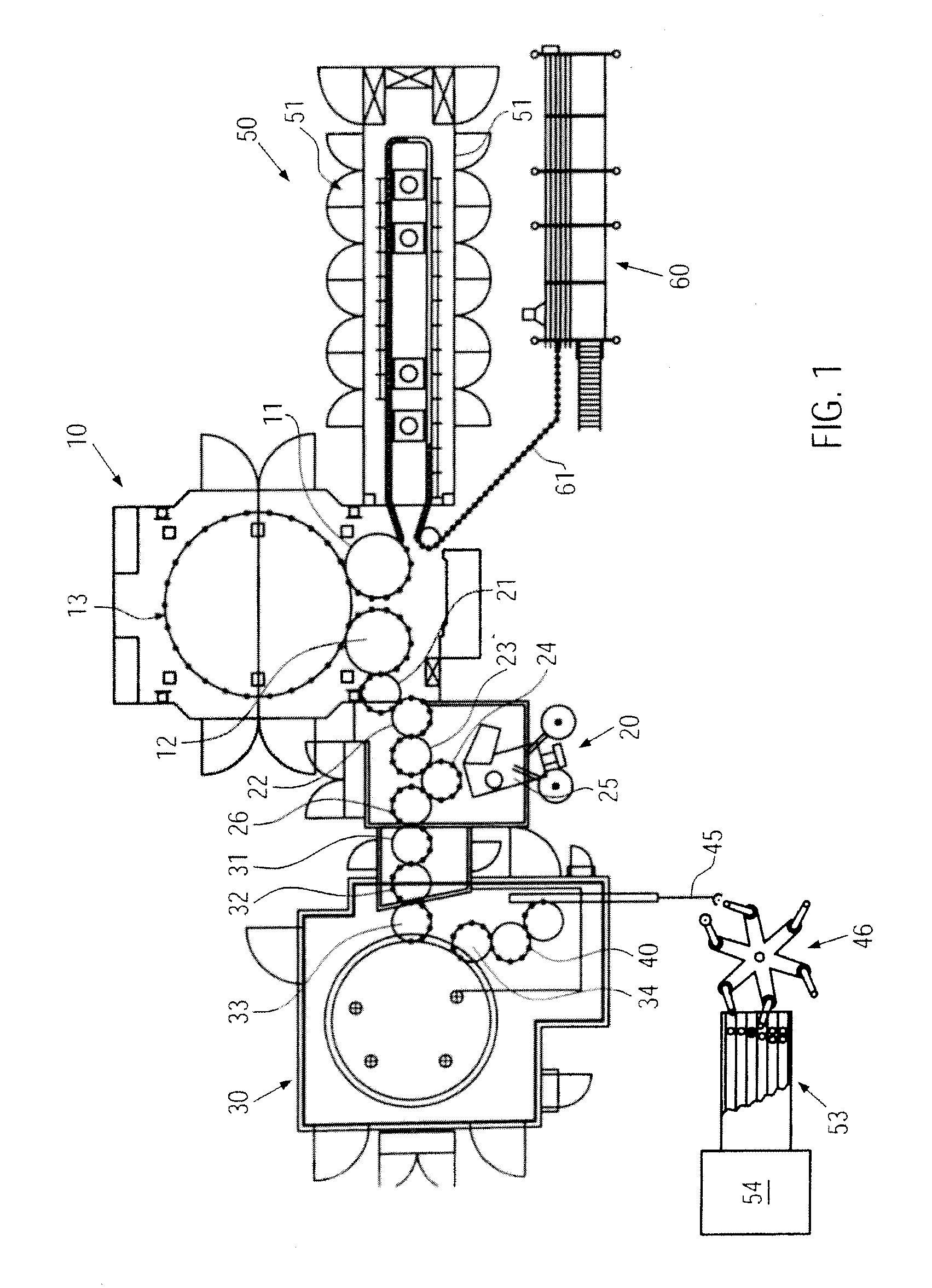
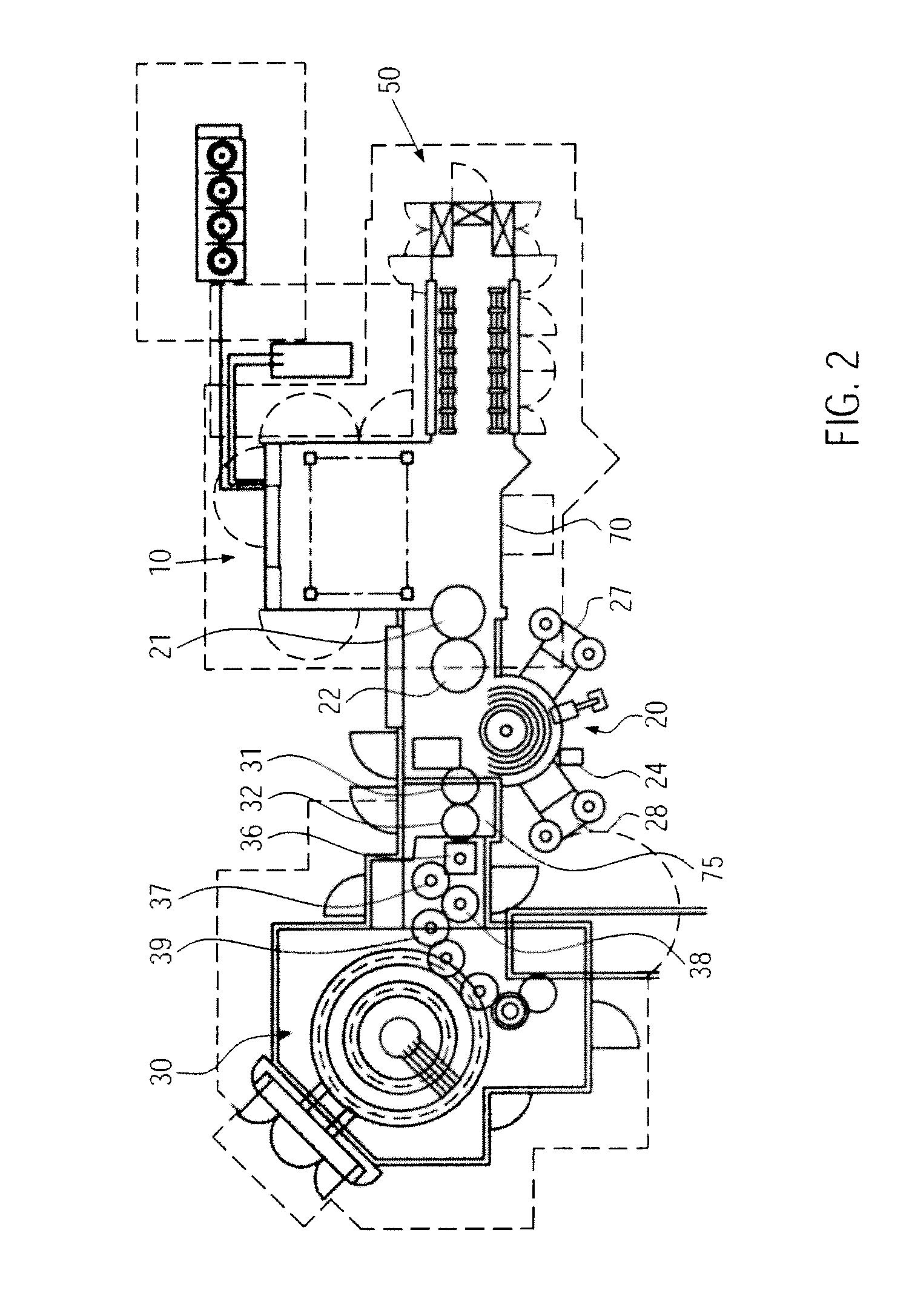
[0008]According to the disclosure the individual machines are thus directly interconnected, i.e. bloc-synchronized, via transfer starwheels. The transfer of the containers between the individual machines takes place via said starwheels, so that although the machines can be arranged in direct vicinity with each other without any long intermediate transportation belts, or the like, separation points are so to speak formed between the machines in the area of the transfer starwheels, which permits a flexible adaptation to different functions. Furthermore, transfer points may be provided in the area of the transfer starwheels for discharging and / or introducing containers so as to e.g. discharge useless or unneeded containers or to fill gaps. Especially in the case of transfer wheels with selectively controllable grippers, this can be realized without any problems. Such transfer points are of particular advantage in the area between a blow molding machine and one of the downstream machines.
[0011]Advantageously, the whole apparatus is configured with the individual machines and transfer starwheels in such a way that a continuous, particularly constant, neck handling plane is also obtained for different bottle sizes or heights. It is intended in a further advantageous configuration of the disclosure that transportation and transfer from the blow molding machine takes place while maintaining the orientation or alignment in the removal position of the bottles from the blow mold up to the labeler for a position-correct labeling. With this measure an aligning or orienting process of the bottles for the position-correct infeed into the labeler is simplified or can be omitted altogether and additional aligning paths need not be provided, which in turn shortens the conveyor path.
[0012]In a further advantageous configuration of the disclosure it is intended that the transfer starwheels are configured as individual modules with their own drive and standard interface. Hence, the transfer starwheels form interfaces with respect to the upstream and / or downstream machines and, thanks to their individual drives (e.g. servomotors, mechanical coupling with decoupling function, or the like), they can decouple the machines from each other. For instance, when a transfer starwheel between the blow molding machine and the labeler is stopped, a decoupling between blow molding machine and labeler can take place, which is e.g. of advantage for eliminating a disorder. It is thereby made possible that e.g. machines that are still operative can be run in an empty state whereas e.g. the upstream ones are stopped. For instance, preferably the blow molding machine can still be run in an empty state while the labeler is stopped, e.g. by way of bottle ejection. This solution also offers a typing function for eliminating the malfunction without the need for running the upstream or downstream machines. Also in the case of retooling an operation of the individual machines independently of the others is of advantage. Finally, since the machines can be decoupled, it is also possible to improve operator protection because the transfer starwheels between adjoining machines can then be disabled, thereby reducing the risk of squeezing or drawing-in.
[0014]In a further advantageous configuration of the disclosure, the labeler is configured as a modular machine with change units for labeling, printing, aligning and / or inspection. When the labeler is configured in this way, the variable usability of the whole apparatus is enhanced because different labeling functions can then be realized in a simple way on the labeler by just changing the labeling units.
[0015]When the further treatment machine is a filler / capper combination which is bloc-synchronized via at least two transfer starwheels with the labeler, this will yield the aforementioned advantages also between treatment machine and filler / capper combination. There are short distances or paths while an independent stopping of the individual machines is nevertheless possible.

Problems solved by technology

In general, there are long transfer paths between these different machines, partly also with interposition of buffers, so that facilities of that type are made relatively extensive, i.e. they need quite a lot of space.

Method used


Image

  • Apparatus and Method for Producing Plastic Bottles
  • Apparatus and Method for Producing Plastic Bottles
  • Apparatus and Method for Producing Plastic Bottles

Examples


Embodiment Construction

[0022]The apparatus according to the disclosure comprises various machines for producing, labeling and, in the illustrated example, for filling and capping plastic bottles. In detail, the illustrated apparatus comprises—in the sequence of the individual treatment stages—a preform supply 60, a heater 50, the blow molding machine 10, the labeler 20 and the filler / capper combination 30, 40 as well as a downstream controlled distribution starwheel 46 that transfers the bottles arriving at the discharge belt 45 in a single row to the multi-track discharger 53. The discharger 53 may already be part of a subsequent packer 54, which is e.g. designed for the groupwise packing of bottle packs in shrink film and / or a carton blank. The packer may e.g. be designed in conformity with DE 42 07 725 A1 and / or DE 44 41 700 A1, i.e. preferably with neck guides for the at least sectionwise suspended transportation of bottles. However, conventional packing machines with bottom-supported bottle transport...


PUM

PropertyMeasurementUnit
Pressureaaaaaaaaaa
Sizeaaaaaaaaaa

Abstract

A method and an apparatus for producing plastic bottles, including a blow molding machine, a labeler, at least one further treatment machine, and transfer starwheels provided and arranged for the machine-to-machine transportation of the bottles in such a way that the bottles are transported without buffers between the at least three machines.

Description

CROSS-REFERENCE TO RELATED APPLICATION[0001]The present application claims the benefit of priority of German Application No. 102009040363.9, filed Sep. 7, 2009. The entire text of the priority application is incorporated herein by reference in its entirety.FIELD OF THE DISCLOSURE[0002]The present disclosure relates to an apparatus and to a method for producing plastic bottles with a blow molding machine, a labeler and at least one further treatment machine, such as a rinser, sterilizer, filler, capper, or the like.BACKGROUND[0003]It is standard in the manufacture of labeled plastic bottles that plastic bottles are first produced in a rotary-type blow molding machine in a continuous way from blanks. The blow molding machine accommodates the heated blanks, also called preforms, in correspondingly designed blow molds in which these are then blown during rotation of the blow molding machine under high pressure and at a high temperature to form bottles.[0004]In known methods, the bottles...

Claims


Application Information

Patent Timeline
IPC IPC(8): B67C7/00B65G37/00B29C49/00
CPCB29C49/06B29C49/36B67C2003/227B67C7/002B67C7/004B29C49/6418B65G29/00B65G47/24B29C49/00B29C49/24B29C49/4273B29C49/64B29C49/6409B65C9/06B65G47/84B29C49/42069B29C49/42087B29C49/42095B29C49/42808B29C2949/0715
Inventor KLENK, CHRISTOPHHAUSLADEN, WOLFGANG
Owner KRONES AG
Why Eureka
Try Eureka