
Continuous driver with changeable parameters

Active Publication Date: 2011-03-03
ERGOSURGICAL GRP CORP
View PDF25 Cites 11 Cited by
  • Summary
  • Abstract
  • Description
  • Claims
  • Application Information

AI Technical Summary

Benefits of technology

[0021]The present invention achieves the combination of several systems in a single apparatus wherein several interactive portions are provided with changeable circumference properties wherein at the same time the apparatus provides distal ends with linear sequence control movement and / or a rotational movement in order to facilitate and efficiently speed up several procedures such as suturing, grasping, cutting, wiring and other procedures that interact with a material such as but not limit to tissues, textile, wires and others.
[0036]Furthermore, the present invention overcomes the inability of the prior art to foresee the need of an ergonomic suturing needle driver that permits left and right handed users to performed safe suturing procedures. The present apparatus is intended to provide an ergonomic suturing device comprising: (i) a plurality of needle driving points located in premeditated positions such that movement of the needle through the points completes one cycle of the suturing procedure; and (ii) a geared mechanism that allows the suturing procedure to be executed with the rotation of a single knob.

Problems solved by technology

It is undoubted that each and every step on any surgical procedure is of great importance and could cause negative consequences for the patient if it is inadequately performed.
The suturing procedure, in particular, could end in serious consequences for the patient if negligently conducted, causing damages to adjacent tissues or even organs.
It is known that the suturing procedure consumes a considerable amount of time of the surgical treatment.
With the increasing cost of healthcare, a new device and procedure are needed to simplify the suturing procedure and reduce the time required for the process, without sacrificing the quality and precision required for delicate sutures.
In these cases, complications arise due to the amount of time the patient has to wait for treatment with an open wound.
Open wounds are susceptible to infection and could result in serious blood loss.
One of the generally unattended deficiencies of the available needle drivers is the handedness of its designs.
The locking mechanisms and the direction of the curves at the end of the needle drivers are not designed for use by left-handed users.
Thus, left handed users have difficulties performing the suturing procedure.
The additional purchases, the additional inventory, and the maintenance of the additional inventory further increases the cost involved with surgical and suturing procedures.
The difficulties encountered by left-handed doctors and hospital personnel increases the risks of negative outcomes for patients from wrong needle driver maneuverings.
The latest improvements to suturing devices often fail at their intention of easing the handling of the device for this reason.
Each step is susceptible to human error.
Completing the cycle is a time-consuming process.

Method used


Image

  • Continuous driver with changeable parameters
  • Continuous driver with changeable parameters
  • Continuous driver with changeable parameters

Examples


first embodiment

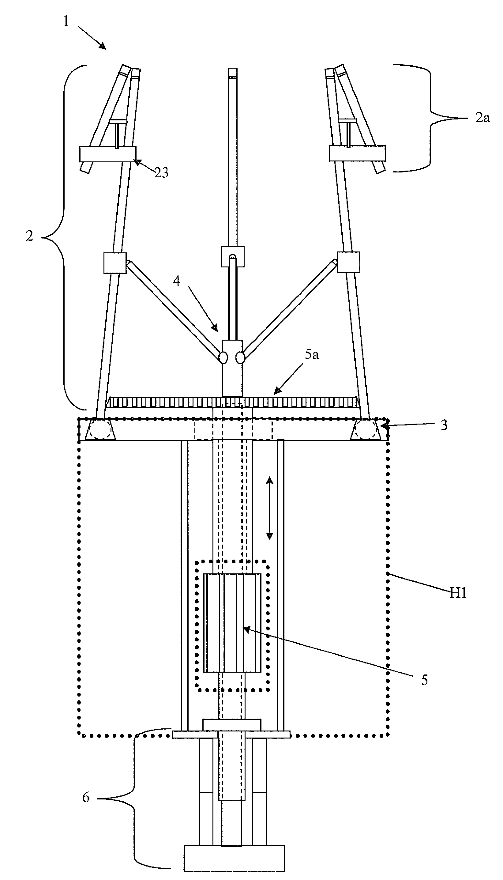
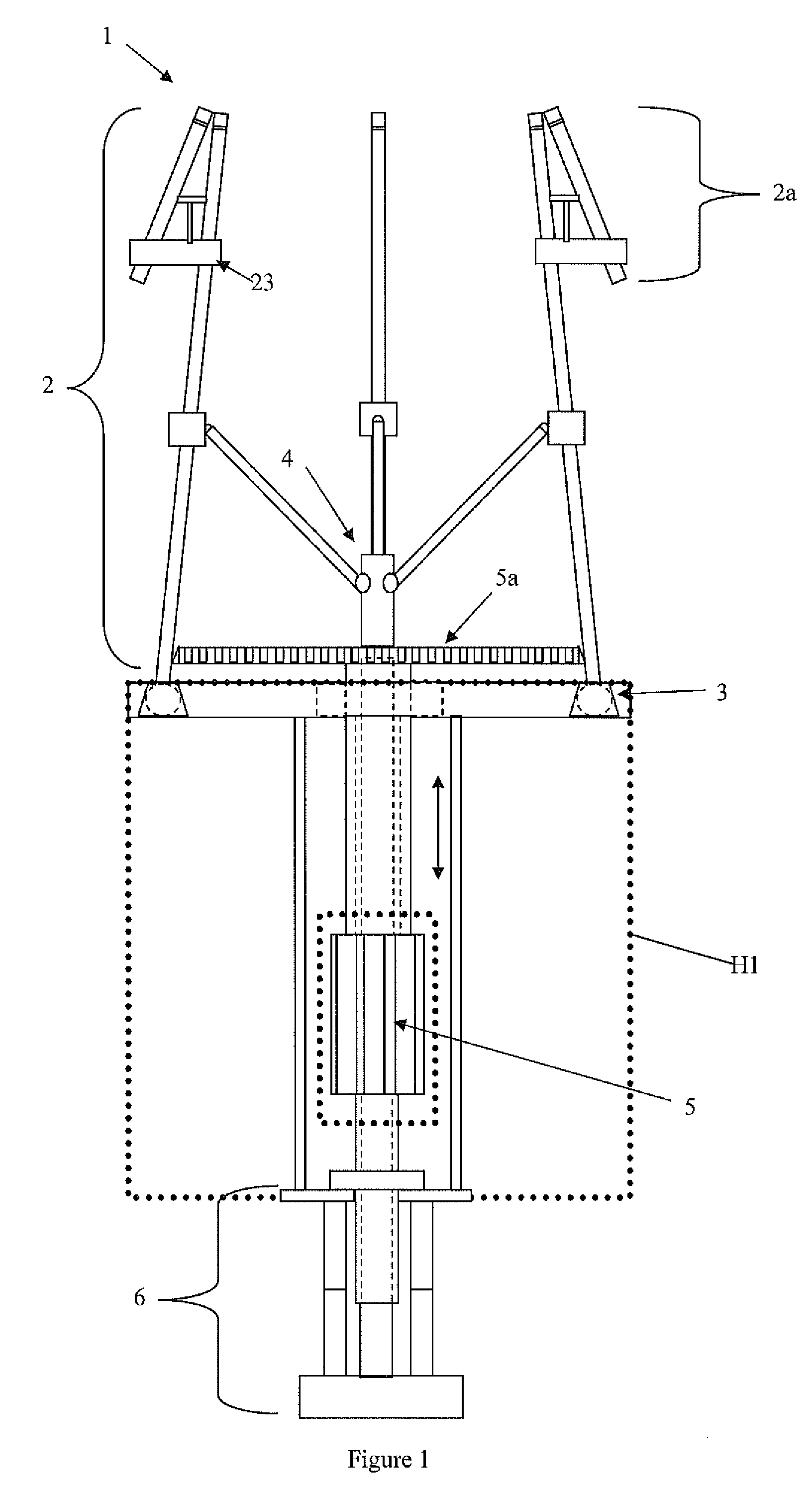
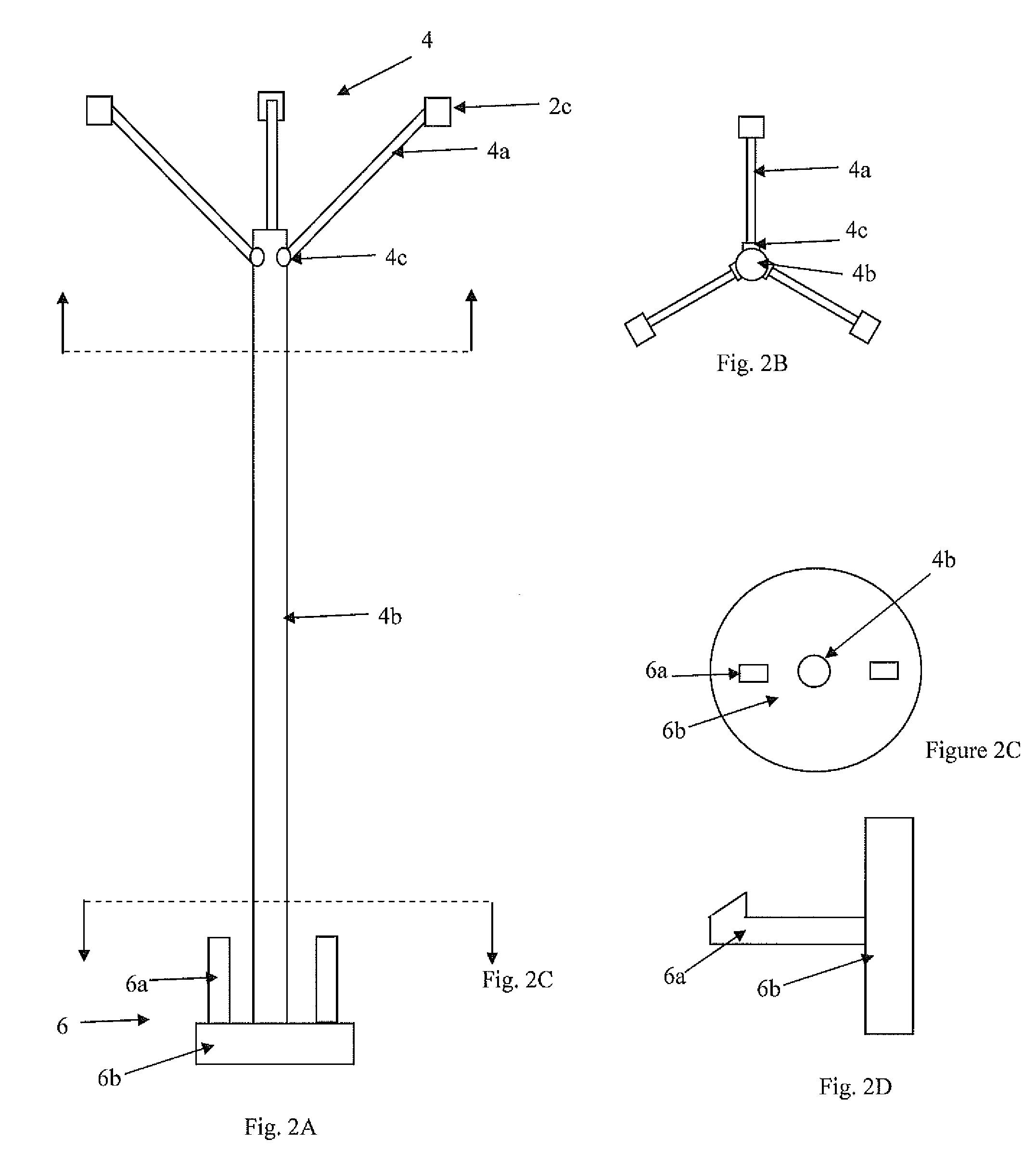
[0073]FIG. 1 shows a first embodiment employing a continuous driver device 1 with changeable parameters as suturing device wherein said continuous driver device comprises a interactive portions 2, a circumference adjuster system 4, locking mechanism 6, a rotational system 5, at least a linear motion system 7, a sequence control system comprising several linear motion systems 7 mechanically connected, and a housing H1 comprising a frame 3. All element or part are made by different material wherein said material are selected depending on the field the device is going to be employed.

[0074]For example, employing the continuous driver 1 as a suturing device requires at least a needle grasping action combined rotational motion in order to produce a continuous circumferential motion of the needle during the suturing procedure. The translation of the needle 11 during continuous circumferential motion is limited to a particular radius, wherein said particular or preferred radius depend most ...

second embodiment

[0092]FIGS. 13-17 shows the circumference adjustment mechanism 3′ including a locking mechanism in order to maintain the desired circumference for the device 1′. FIG. 13 shows a second embodiment wherein the interactive housing 2000 is mechanically coupled to single way circumference adjuster including a locking mechanism and to the rotational system by means of the main gear 5a. FIG. 14 shows the rotational system 5″ couple to the circumference adjuster 8 including a locking mechanism by means of the main gear 5a. FIG. 15 is directed to show the non-rotational plate 5e which is connected to the frame or housing H2 to support part circumference adjustment mechanism gears 8. The rotational system extension 5b′ passes through said non-rotational plate 5e in order to contact the main gear 5a.

[0093]FIG. 16 shows the circumference adjustment mechanism gears 8 comprising a secondary gears 8a, a third gear 8b coupled to a rotation distal end gear 8e, a movable body 8c and a movable attach...

third embodiment

[0099]FIGS. 20-21 are directed to the distal end arrangement of the slave rod 210 and driven rod 211. FIG. 20 shows the driven and slave rods 200, 210 are positioned in parallel to the longitudinal axis of the device 1′. The slave rod 210 is pivoted near at the contact distal end 2a′, such that the ends of slave rods 210 are positioned obliquely with respect to the driven rods 200. FIG. 20A shows the first extended hollow cylinder 2002 comprising a protrusion 2104 extended perpendicular to the slave rod 210 and positioned at the inner surface of said hollow cylinder 2002. The main purpose of the protrusion is to be combined with the linear movement of the slave rod 210 and increase the grasping force at the contact distal end 28. A distal end resilient material 2103 is located at the inner surface of said hollow cylinder 2002 substantially facing or at least providing some resistance to the force exerted by the protrusion 2104 over the slave rod 210 when the slave rod is pushed to t...


PUM


Abstract

The present invention relates generally to continue driver device with changeable parameters, more specifically, continues driver with changeable parameters used in surgical procedure such as suturing, wherein said continues driver device is employed in as continuous suture rotational needle driver which enhances the tissue suturing procedure, particularly the one performed on restricted, deep and less accessible locations. The device incorporates a plurality of interactive portion comprising several extended member wherein in said extended members are provided with rotational needle driving points at a distal end into a single device and is operated by the twist of a single knob. The use of the mechanism prevents problems associated with loss of needle control during the suturing procedure as well as the ones associated with the handedness of existing needle drivers.

Description

RELATED APPLICATIONS[0001]N / ABACKGROUND OF INVENTION[0002]1. Field of the Invention[0003]The present invention relates generally to a continuous driver device with changeable parameters, more specifically, to a continuous driver with changeable parameters to be used in surgical procedure such as suturing, wherein said continuous driver device is employed in a continuous suture rotational needle driver which enhances the tissue suturing procedure. The device incorporates a plurality of interactive portions into a single device, each portion comprising several extended members wherein in said extended members are provided with rotational needle driving points at a distal end, and is wherein the device is operated by a actuator mechanism. The use of the mechanism prevents problems associated with loss of needle control during the suturing procedure as well as the ones associated with the handedness of existing needle drivers. It also enhances the control a surgeon has over the suturing...

Claims


Application Information

Patent Timeline
IPC IPC(8): A61B17/062A61B17/04
CPCA61B17/0482A61B2017/00398A61B17/0491
Inventor ALMODOVAR, LUIS JOSE
Owner ERGOSURGICAL GRP CORP
Learn More