Wire facing unit for retaining walls with strut attachment locator

a technology of retaining wall and locator, which is applied in the direction of mining structures, excavations, artificial islands, etc., can solve the problems of poor construction technique, difficult face stability, weakened temporary retaining wall structure, and difficult to meet the needs of construction, etc., to achieve easy and inexpensive construction, easy and inexpensive form, and easy and accurate installation

Active Publication Date: 2011-03-03
TENSAR CORPORATION LLC
View PDF11 Cites 2 Cited by
  • Summary
  • Abstract
  • Description
  • Claims
  • Application Information

AI Technical Summary

Benefits of technology

[0009]A further object of this invention is the provision of a wire facing unit formed from welded wire having a built-in structural locator or indicator arrangement that enables the installer to precisely locate the wire struts to be installed between the face section and floor section of the wire facing unit. Specifically, it is an object of the present invention to provide a wire facing unit wherein the floor section includes pairs of parallel wires that define the location where the wire facing strut is to be connected to the floor section.
[0010]A still further object of this invention is to provide an assembly of elements to easily and inexpensively form a retaining wall section with a precise location of wire connecting struts requiring the use of no extraneous materials or tools and enabling installation quickly, easily and accurately.

Problems solved by technology

One of the main areas for poor construction technique is the wall or slope face.
However, face stability, compaction and geosynthetic placement is very difficult in wall and steep slope applications without the use of an effective face forming system employing wire facing units.
The installer may be told or instructed to install the wire struts at predetermined locations, for example every two feet, but errors in locating the wire struts can occur such that the wire struts may be located further apart from the required spacing, thus resulting in a weakened temporary retaining wall structure.
The known wire facing unit (sometimes referred to as a basket) while simple, does not provide the installer an easy way to make sure that the support struts are installed in the proper location.
It is very common for the installer to space the struts beyond the predetermined maximum spacing requirement (i.e., beyond the prescribed two foot spacing) which can lead to excessive bulging beyond the current AASHTO allowance.

Method used


Image

  • Wire facing unit for retaining walls with strut attachment locator
  • Wire facing unit for retaining walls with strut attachment locator
  • Wire facing unit for retaining walls with strut attachment locator

Examples


Embodiment Construction

[0018]In describing a preferred embodiment of the invention illustrated in the drawings, specific terminology will be resorted to for the sake of clarity. However, the invention is not intended to be limited to the specific terms so selected, and it is to be understood that each specific term includes all technical equivalents which operate in a similar manner to accomplish a similar purpose.

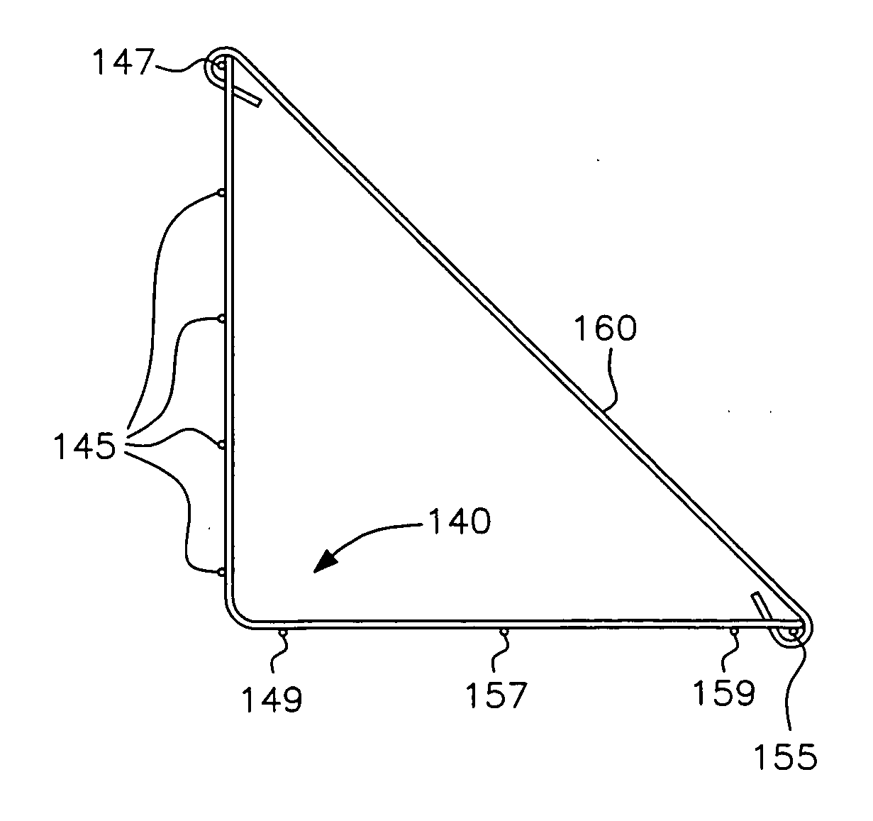
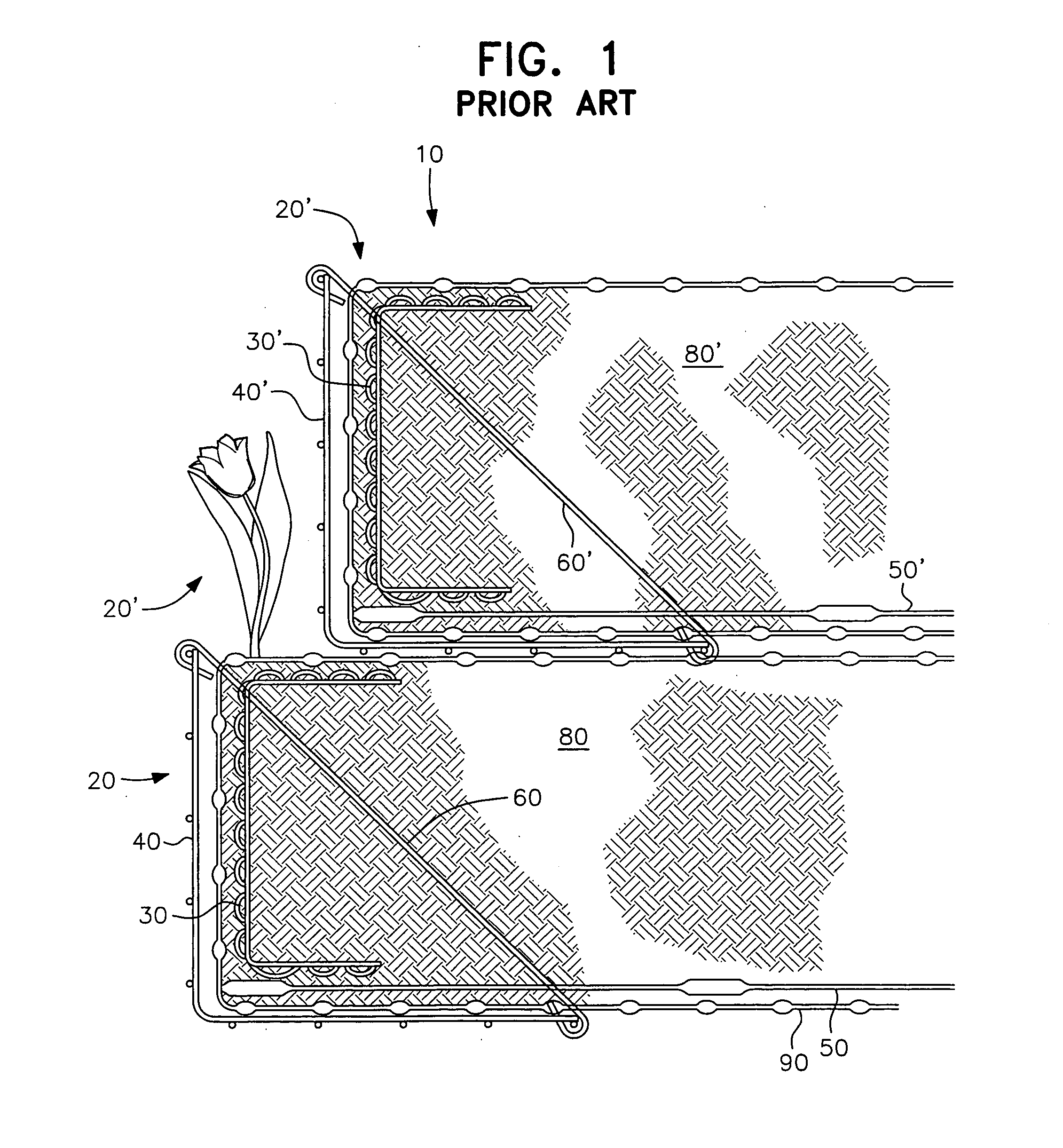
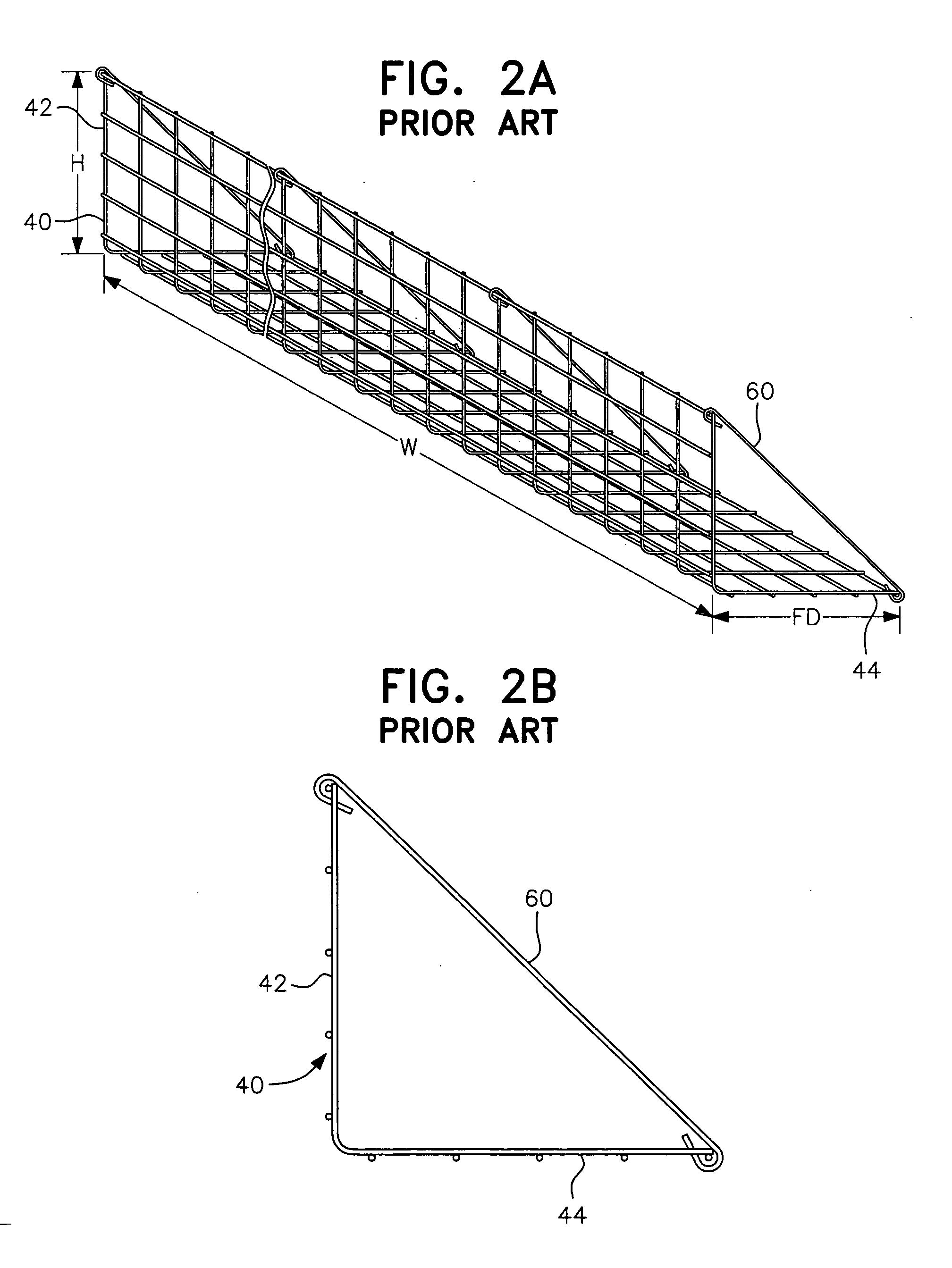
[0019]A retaining wall constructed using a system of the prior art is shown in FIGS. 1 and 2, and indicated generally by the reference numeral 10 in FIG. 1. In this Figure, two tiers or layers 20, 20′ of geogrid-reinforced wall sections are depicted. Of course, although two tiers 20, 20′ are illustrated in FIG. 1, retaining walls can be built of only a single tier or many more than two tiers, depending upon the height of the wall and the dimensions of the elements forming the wall. Not only can the height be variable, but the width of the wall can likewise be variable by providing wire facing un...


PUM


Abstract

A wire strut indicator facing unit for a retaining wall, such as a temporary retaining wall, having an upstanding face section and a rearwardly extending floor section, wherein the floor section is formed from pairs of parallel wire elements and transverse cross-wire elements, and otherwise substantially free of wire elements between the wire element pairs. The pairs of parallel wires define the attachment location for a wire strut that extends between the face section and floor section of the facing unit.

Description

BACKGROUND OF THE INVENTION[0001]1. Field of the Invention[0002]This invention relates to a wire facing unit for retaining walls and reinforced soil slopes that require placement of supporting struts at predetermined spacings along the width of the facing unit. The wire facing unit includes a built-in structural locator arrangement to provide a visual indication or reference for the installer to place the supporting struts at the correct locations.[0003]2. Description of the Related Art[0004]The formation of retaining walls such as Mechanically Stabilized Earth Walls (MSEW) and Reinforced Soil Slopes (RSS) and the use of reinforcing materials, such as geogrids for such structures is well known. The success of these structures relies not only on the reinforcing materials, but also on the manner in which the MSEW and RSS structures are installed. One of the main areas for poor construction technique is the wall or slope face. Under current design guidelines of the American Association...

Claims


Application Information

Patent Timeline
Patent Type & Authority Applications(United States)
IPC IPC(8): E02D17/00E04H12/08
CPCE02D29/02
Inventor RIDGWAY, JON ROBERT
Owner TENSAR CORPORATION LLC
Why Eureka
Try Eureka