
Generation of electric energy using cable-supported windmills

a technology of electric energy and windmills, which is applied in the direction of electric generator control, renewable energy generation, greenhouse gas reduction, etc., can solve the problems of difficult to fully convert the power that each windmill can individually generate, the optimal orientation of a windmill suspended between cables can also be lost, and the difficulty of effective and economical implementation

Active Publication Date: 2011-03-03
UNIV OF SOUTHERN CALIFORNIA
View PDF80 Cites 21 Cited by
  • Summary
  • Abstract
  • Description
  • Claims
  • Application Information

AI Technical Summary

Benefits of technology

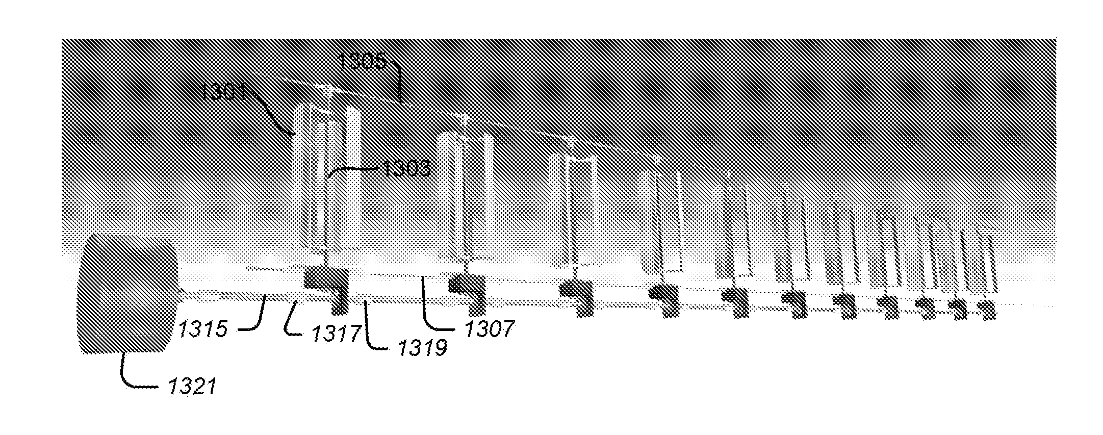
[0006]An electric energy generation system may include a plurality of windmills, a windmill support system, an electric generator, and a coupling system. The windmills may each be configured to transform wind energy into rotational energy. The windmill support system may support the windmills in positions that are spaced apart from one another. The electric generator may be configured to transform rotational energy into electric energy. The coupling system may be configured to couple the rotational energy generated by each of the windmills to the electric generator in a manner that permits the windmills to rotate at different speeds during operation of the electric energy generation system.

Problems solved by technology

Such systems, however, can be challenging to implement effectively and economically.
For example, it can be difficult to fully convert the power that each windmill can individually generate when they are configured to drive a common shaft coupled to a common electric generator.
The optimal orientation of a windmill suspended between cables can also be lost when the windmill twists during operation.
Heavy electric generators can also be challenging to suspend from inexpensive cables.
It may also be difficult to combine the outputs of several windmills that rotate about a horizontal axis in order to drive a common electric generator.
Guying each tower that supports windmill cables can also be costly and wasteful of land.

Method used


Image

  • Generation of electric energy using cable-supported windmills
  • Generation of electric energy using cable-supported windmills
  • Generation of electric energy using cable-supported windmills

Examples


Embodiment Construction

[0039]Illustrative embodiments are now described. Other embodiments may be used in addition or instead. Details which may be apparent or unnecessary may be omitted to save space or for a more effective presentation. Some embodiments may be practiced with additional components or steps and / or without all of the components or steps which are described.

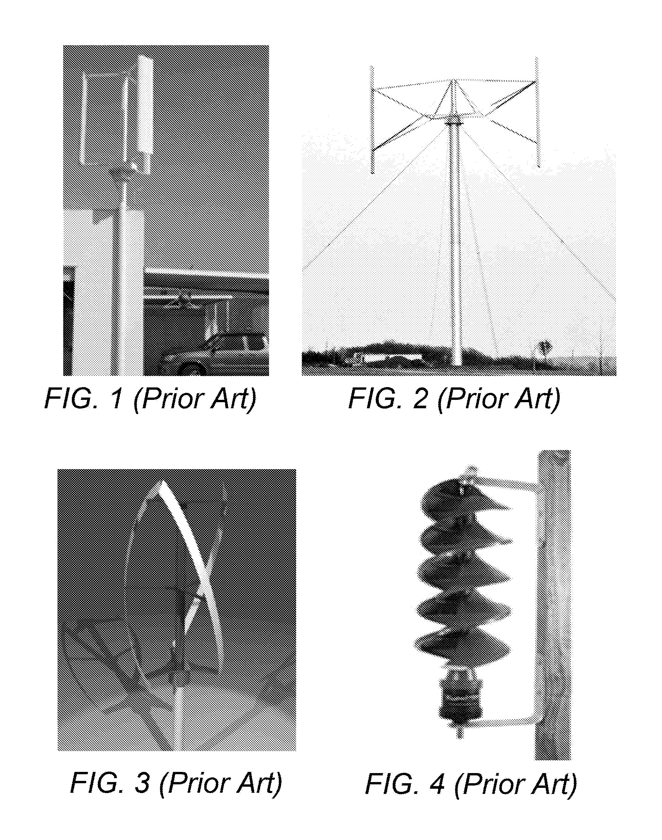
[0040]FIGS. 1-6 illustrate prior art windmills which rotate about a vertical axis. These windmills may effectively catch wind coming from any horizontal direction. However, their supports can be costly to build, particularly when a large number are needed. FIGS. 3-6 also illustrate prior art windmills which can catch wind traveling in both the vertical and horizontal directions.

[0041]FIG. 7 illustrates a windmill and associated electric generator which are both supported by two substantially parallel cables. As illustrated in FIG. 7, a windmill 701 may be configured to rotate about a vertical shaft 703 which drives an electric generator ...


PUM


Abstract

An electric energy generation system may include a plurality of windmills, a windmill support system, an electric generator, and a coupling system. The windmills may each be configured to transform wind energy into rotational energy. The windmill support system may support the windmills in positions that are spaced apart from one another. The electric generator may be configured to transform rotational energy into electric energy. The coupling system may be configured to couple the rotational energy generated by each of the windmills to the electric generator in a manner that permits the windmills to rotate at different speeds during operation of the electric energy generation system. Other configurations are also disclosed.

Description

CROSS-REFERENCE TO RELATED APPLICATION[0001]This application is based upon and claims priority to U.S. provisional patent application 61 / 239,019, entitled “CABLE BASED INSTALLATION OF WINDMILLS FOR ELECTRIC ENERGY GENERATION,” filed Sep. 1, 2009, attorney docket number 028080-0503. The entire content of this application is incorporated herein by reference.BACKGROUND[0002]1. Technical Field[0003]This disclosure relates to the generation of electric energy using cable-supported windmills.[0004]2. Description Of Related Art[0005]Windmills suspended by cables have been proposed for the generation of electric energy. Such systems, however, can be challenging to implement effectively and economically. For example, it can be difficult to fully convert the power that each windmill can individually generate when they are configured to drive a common shaft coupled to a common electric generator. The optimal orientation of a windmill suspended between cables can also be lost when the windmill ...

Claims


Application Information

Patent Timeline
IPC IPC(8): F03D9/00
CPCF03D11/04F05B2240/213F05B2240/40F05B2240/911Y02E10/728F05B2250/25F05B2260/4031F05B2260/406F05B2240/917F03D13/20Y02E10/74F03D9/255F03D15/10F03D9/28F03D3/02
Inventor KHOSHNEVIS, BEHROKH
Owner UNIV OF SOUTHERN CALIFORNIA
Learn More