Image forming apparatus and transfer apparatus
- Summary
- Abstract
- Description
- Claims
- Application Information
AI Technical Summary
Benefits of technology
Problems solved by technology
Method used
Image
Examples
first embodiment
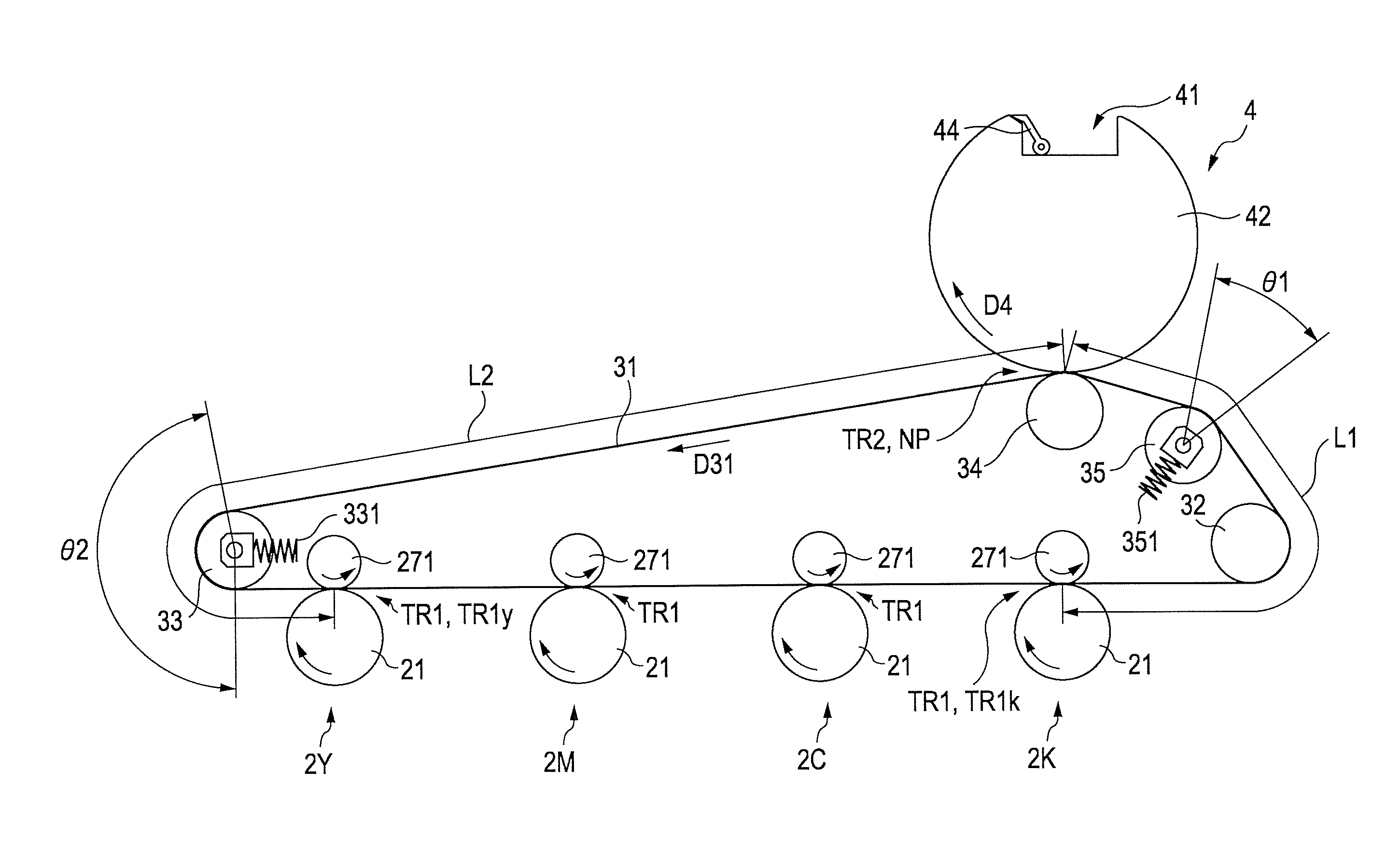
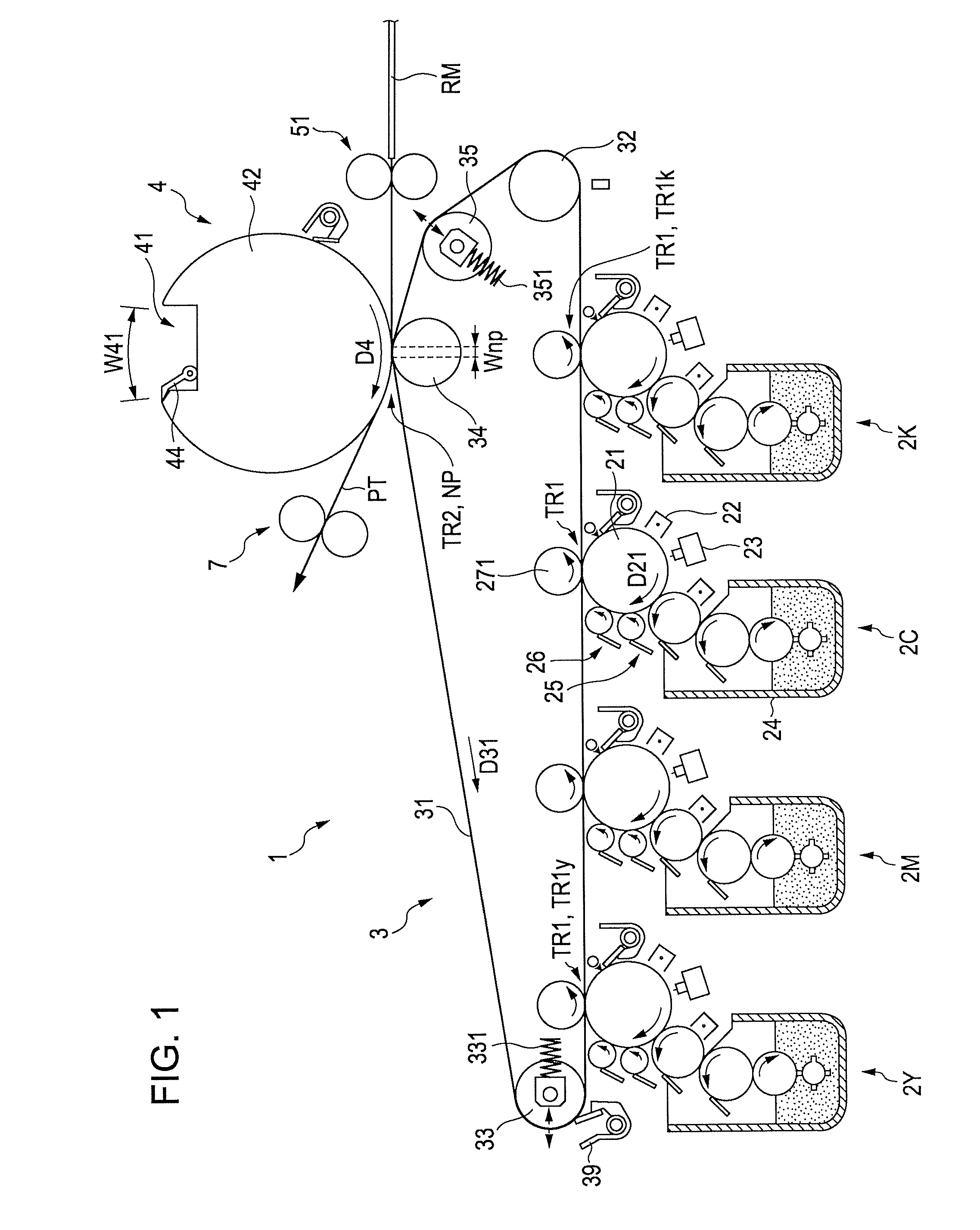
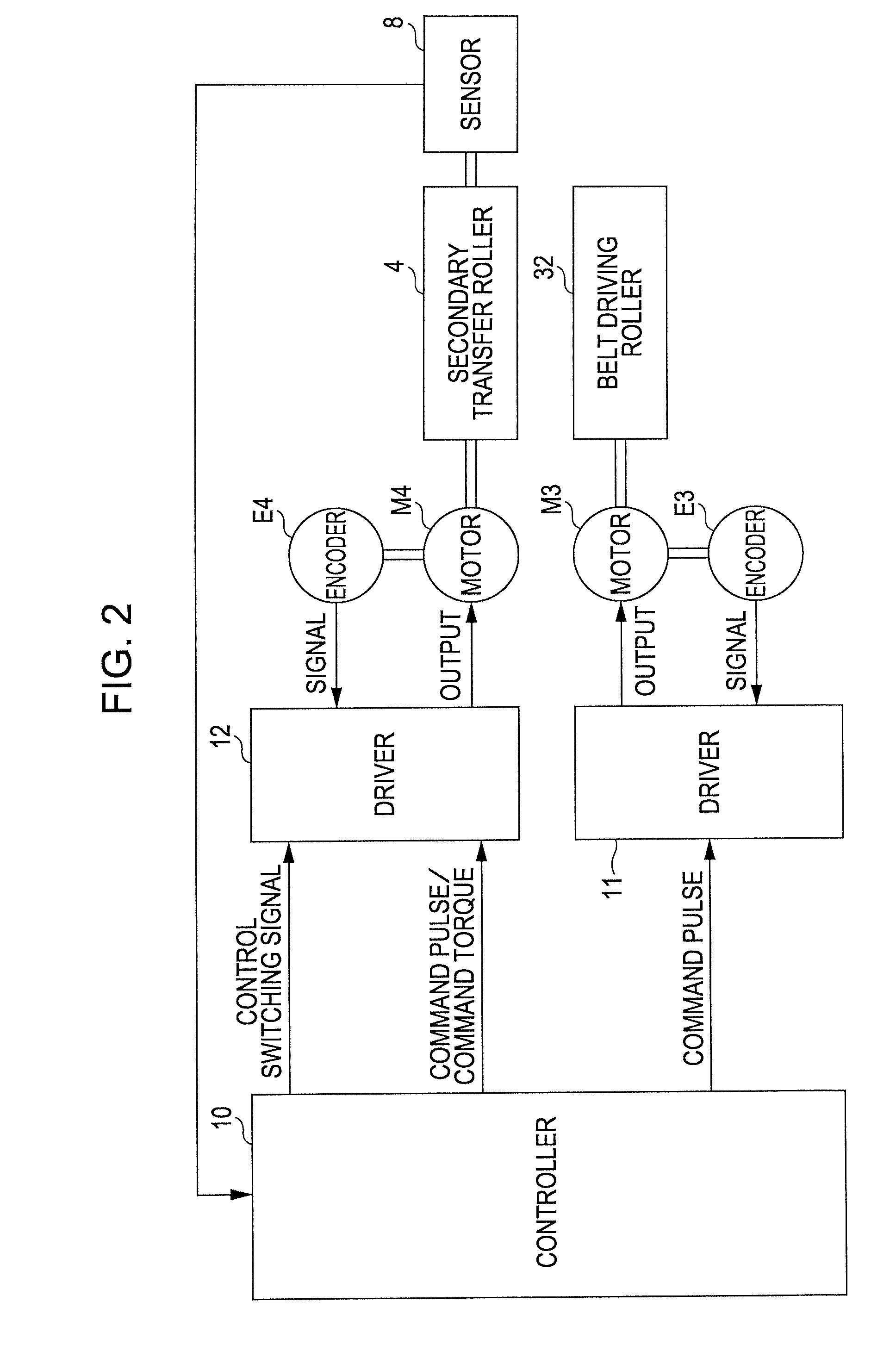
[0038]FIG. 1 illustrates an image forming apparatus 1 according to the invention. FIG. 2 is a block diagram illustrating the electrical configuration of the image forming apparatus 1 illustrated in FIG. 1. The image forming apparatus 1 is provided with four image forming stations including 2Y (for yellow), 2M (for magenta), 2C (for cyan), and 2K (for black), each station forming an image of different colors. Toners of four colors including yellow (Y), magenta (M), cyan (C), and black (K) are used in combination to form a color image, and only a toner of black (K) is used to form a black-and-white image. The image forming apparatus 1 is capable of selectively performing the color print and the black-and-white print. In this image forming apparatus, in cases where a controller 10 having a central processing unit (CPU) and a memory receives an image forming instruction from an external apparatus such as a host computer, the controller 10 controls each section of the image forming appar...
second embodiment
[0101]An image forming apparatus according to the invention will be described with reference to FIGS. 9 and 10.
[0102]FIG. 9 illustrates the image forming apparatus according to the second embodiment of the invention. FIG. 10 illustrates arrangement of rollers according to the second embodiment in more detail. In the first embodiment, the tension roller 33 is disposed at a position in the vicinity of an upstream side relative to the image forming station 2Y positioned in the most upstream side. On the other hand, in the image forming apparatus la according to the second embodiment illustrated in FIG. 9, a driven roller 36 is disposed at a position in the vicinity of the upstream side relative to the image forming station 2Y positioned in the most upstream side, the driven roller 36 has a rotating shaft that does not travel. Furthermore, a tension roller 37 is disposed between the secondary transfer position TR2 and the driven roller 36. In other words, the driven roller 36 is additio...
PUM
 Abstract
Description
Claims
Application Information
 - R&D
- Intellectual Property
- Life Sciences
- Materials
- Tech Scout
- Unparalleled Data Quality
- Higher Quality Content
- 60% Fewer Hallucinations
Browse by: Latest US Patents, China's latest patents, Technical Efficacy Thesaurus, Application Domain, Technology Topic, Popular Technical Reports.
© 2025 PatSnap. All rights reserved.Legal|Privacy policy|Modern Slavery Act Transparency Statement|Sitemap|About US| Contact US: help@patsnap.com


