
Light pulse generator and optical time domain reflectometer using the same

a technology of light pulse generator and reflectometer, which is applied in the direction of instruments, semiconductor lasers, testing fibre optic/optical waveguide devices, etc., can solve the problems of difficult to remove the inductances of components, difficult to generate laser light pulses, and difficult to shorten the width of light pulses

Active Publication Date: 2011-02-24
YOKOGAWA ELECTRIC CORP
View PDF2 Cites 12 Cited by
  • Summary
  • Abstract
  • Description
  • Claims
  • Application Information

AI Technical Summary

Benefits of technology

The present invention provides a light pulse generator and an optical time domain reflectometer that can output a light pulse with a steep rising edge. The light pulse generator includes a laser diode, a voltage source, a switching element, and an auxiliary current circuit. The optical time domain reflectometer uses the light pulse generator to measure characteristics of an optical fiber based on the return light of the light pulse. The technical effects of the invention include improved accuracy and reliability in optical fiber measurements and improved performance of optical time domain reflectometers.

Problems solved by technology

That is, it is difficult to generate a laser light pulse having a steep rising edge using a large current.
Further, it is difficult to remove the inductances of the components 11-15 and the printed circuit board on which they are mounted, and hence shortening of the width of a light pulse becomes more difficult as the necessary LD forward current Id increases (i.e., as the necessary output optical power of the LD 11 increases).

Method used


Image

  • Light pulse generator and optical time domain reflectometer using the same
  • Light pulse generator and optical time domain reflectometer using the same
  • Light pulse generator and optical time domain reflectometer using the same

Examples


second embodiment

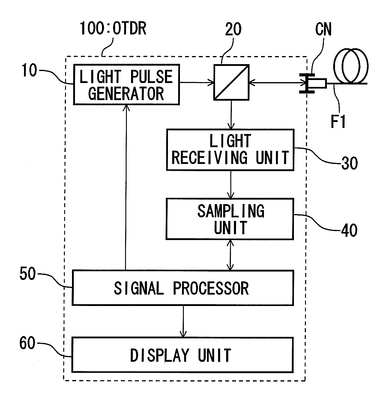
[0073]FIG. 8 is a block diagram showing the configuration of an OTDR which uses the light pulse generator of FIG. 1. In FIG. 8, a measurement subject optical fiber F1 is a line for transmitting an optical signal.

[0074]The OTDR 100 has, at the entrance / exit end, a measurement connector CN to which the measurement subject optical fiber F1 is connected. Light pulses are input to the measurement subject optical fiber F1 from the measurement connector CN. Return light beams (reflection light beams or back scattering light beams) of the light pulses that are input to the measurement subject optical fiber F1 are input to the OTDR 100 via the measurement connector CN.

[0075]The OTDR 100 is equipped with the light pulse generator 10 of FIG. 1, a directional coupler 20, a light receiving unit 30, a sampling unit 40, a signal processor 50, and a display unit 60. The light pulse generator 10 inputs light pulses to the measurement subject optical fiber F1 via the directional coupler 20 and the me...


PUM

PropertyMeasurementUnit
bias voltageaaaaaaaaaa
constant currentaaaaaaaaaa
constant voltageaaaaaaaaaa

Abstract

There is provided a light pulse generator. The light pulse generator includes: a laser diode; a voltage source that provides a bias voltage to the laser diode; a switching element that causes the laser diode to emit a light pulse by directly modulating the laser diode; and an auxiliary current circuit which starts to charge immediately after turn-on of the switching element and which starts to discharge after a forward current flows through the laser diode so as to provide a auxiliary current to the laser diode in the same direction as the forward current.

Description

[0001]This application claims priority from Japanese Patent Application No. 2009-189293, filed on Aug. 18, 2009, the entire contents of which are incorporated by reference herein.BACKGROUND OF THE INVENTION[0002]1. Technical Field[0003]The present disclosure relates to a light pulse generator and an optical time domain reflectometer using the light pulse generator. More specifically, the present disclosure relates to a light pulse generator which outputs light pulses having a steep rising edge and an optical time domain reflectometer using the light pulse generator.[0004]2. Related Art[0005]In optical communication systems which perform a data communication using an optical signal, it is important to monitor optical fibers for transmitting optical signals. An optical time domain reflectometer (hereinafter abbreviated as “OTDR”) is used in installation, maintenance or the like of optical fibers.[0006]The OTDR performs measurements relating to a disconnection, a loss or the like of an...

Claims


Application Information

Patent Timeline
Patent Type & Authority Applications(United States)
IPC IPC(8): G01N21/00H01S3/10
CPCH01S5/0428G01M11/3145
Inventor KOMAMAKI, MORITOSHI
Owner YOKOGAWA ELECTRIC CORP
Learn More