
Magnetic induction signal repeater

a repeater and electromagnetic induction technology, applied in the field of electromagnetic induction radio systems, can solve the problems of limiting the range of mi radio communications and the power of the device itsel

Active Publication Date: 2011-02-24
COCHLEAR LIMITED
View PDF6 Cites 198 Cited by
  • Summary
  • Abstract
  • Description
  • Claims
  • Application Information

AI Technical Summary

Problems solved by technology

Very often the device itself has limited power, which limits the range of the MI radio communications.

Method used


Image

  • Magnetic induction signal repeater
  • Magnetic induction signal repeater
  • Magnetic induction signal repeater

Examples


Embodiment Construction

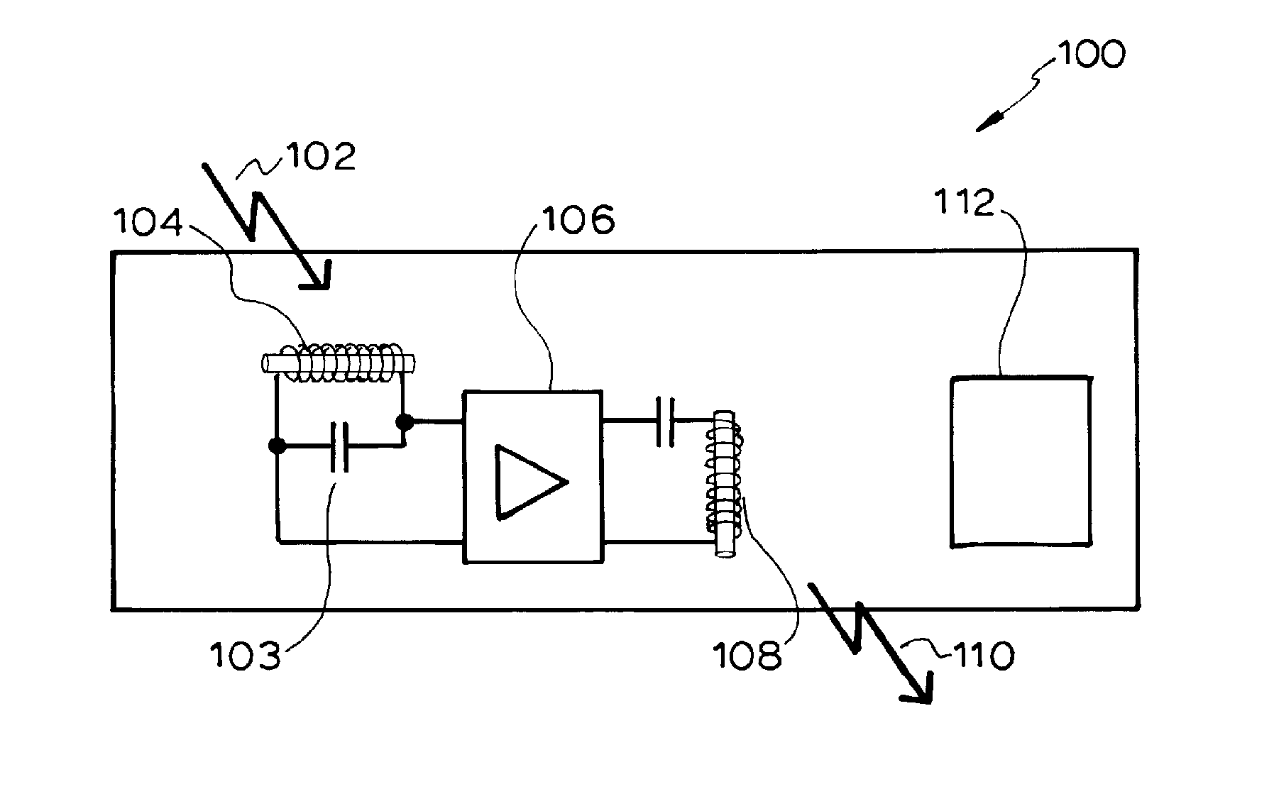
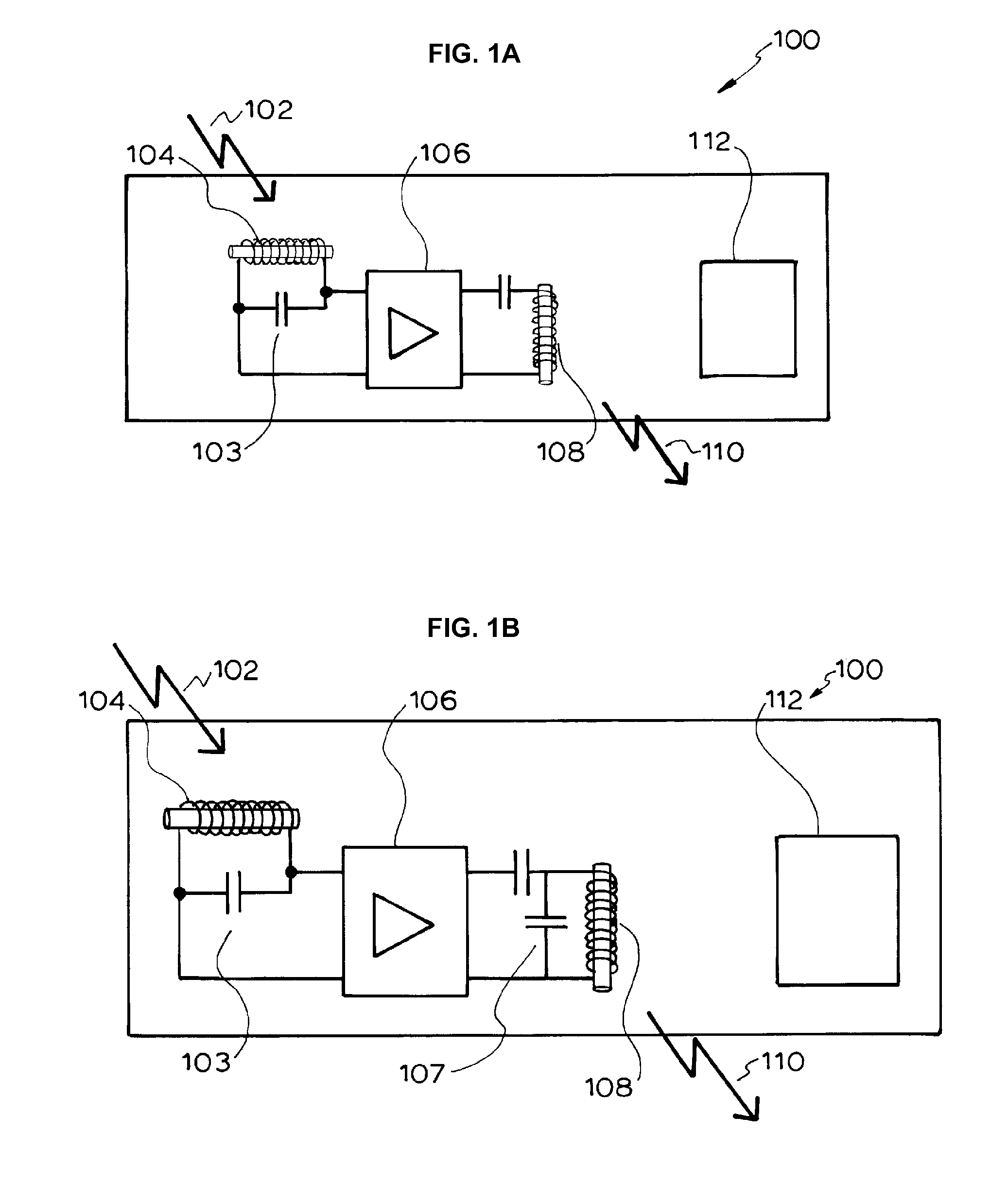
[0024]Broadly, the present invention provides a repeater device which will receive and re-transmit the received MI signal, thereby increasing its range, without substantially modifying the signal.

[0025]According to one aspect, the present invention provides a method of extending the range of a magnetic induction radio system, wherein a magnetic induction repeater is provided.

[0026]According to another aspect, the present invention provides a medical device system, including at least two devices which communicate using MI radio, wherein the system further includes a MI repeater device.

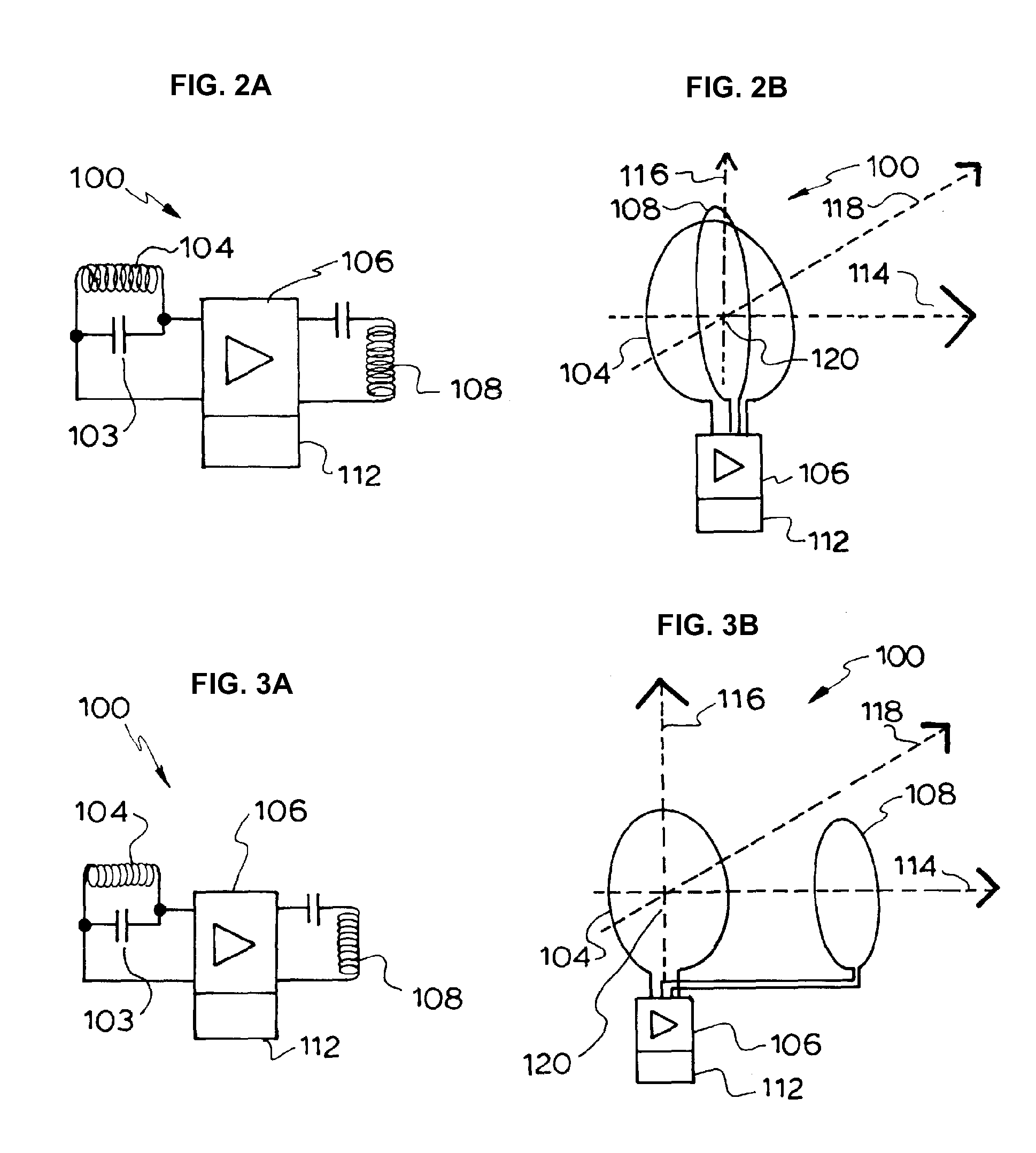
[0027]According to another aspect, the present invention provides a MI repeater, including a receiver coil, a transmitter coil, and an amplifier, the signal induced in the receiver coil being amplified by said amplifier, wherein the transmitter coil and the receiver coil are arranged to be highly isolated.

[0028]The present invention may accordingly be employed to extend the range of the MI system, using...


PUM


Abstract

A magnetic induction (MI) repeater includes first and second coils configured to have the same resonance frequency and to be substantially isolated from one another, and an amplifier connected to the first and second coils and configured to receive a signal induced in the first coil by a first magnetic field and output, via the second coil, a second magnetic field based on the signal, wherein the second magnetic field is amplified relative to the first magnetic field.

Description

CROSS-REFERENCE TO RELATED APPLICATIONS[0001]This application is a National Stage Application of International Patent Application No. PCT / AU2009 / 000523, filed Apr. 28, 2009, which claims the benefit of Australian Provisional Application No. 2008902082, filed Apr. 28, 2008, both of which are hereby incorporated by reference herein.BACKGROUND[0002]1. Field of the Invention[0003]The present invention relates to magnetic induction (MI) radio systems, and particularly to an MI repeater.[0004]2. Related Art[0005]Some medical devices, for example cochlear implants and hearing aids, use magnetic induction (MI) radio to communicate between a device and various associated peripheral devices. For example, it may be used to transmit data to and from a cochlear implant or hearing aid, or to communicate with a remote control. Very often the device itself has limited power, which limits the range of the MI radio communications.[0006]It is an object of the present invention to provide a method and ...

Claims


Application Information

Patent Timeline
IPC IPC(8): H02J17/00H04B7/14
CPCH04B5/263H04B5/24H04B5/266H04W16/26
Inventor MESKENS, WERNER
Owner COCHLEAR LIMITED
Learn More