
Faucet Device Background of the invention

a technology of faucet device and flange, which is applied in the directions of water supply installation, functional valve type, transportation and packaging, etc., can solve the problems that the number of parts or elements cannot be easily and quickly assembled by the users themselves, and achieve the effect of improving and simplifying the structure, making or manufacturing easily and quickly, and facilitating assembly

Inactive Publication Date: 2011-02-24
YANG YU CHIU
View PDF7 Cites 2 Cited by
  • Summary
  • Abstract
  • Description
  • Claims
  • Application Information

AI Technical Summary

Benefits of technology

[0010]The primary objective of the present invention is to provide a faucet device including an improved and simplified structure for allowing the faucet device to be easily and quickly made or manufactured and to be easily and quickly assembled by the users themselves.
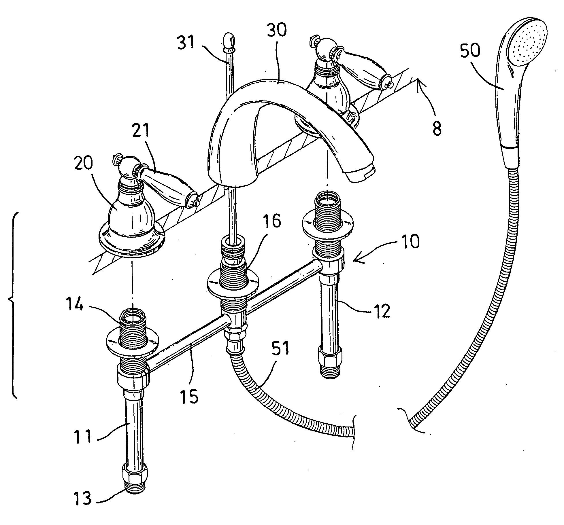
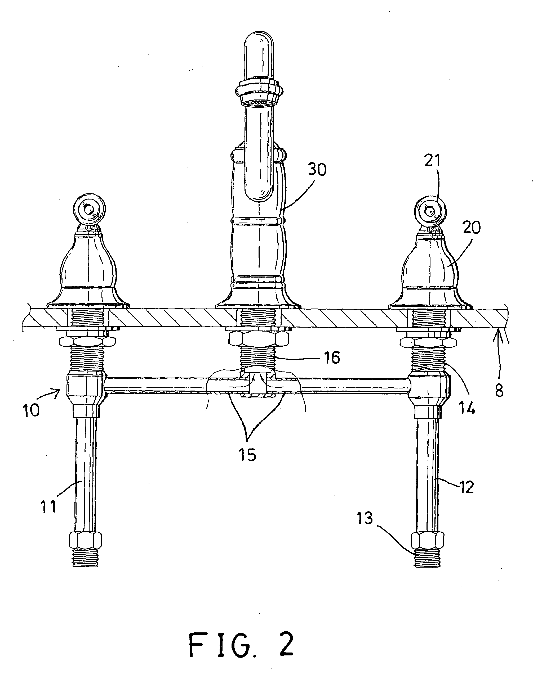
[0011]In accordance with one aspect of the invention, there is provided a faucet device comprising a connector assembly including two tubes spaced from each other, and the tubes each including a lower portion for receiving a cold water and a hot water respectively and each including an upper portion, a connector pipe disposed and coupled between the tubes and solidly secured to the tubes for forming an H-shaped structure, and a mixing pipe attached and mounted to the connector pipe for receiving the cold water and the hot water from the tubes respectively and for allowing the cold water and the hot water to be mixed within the mixing pipe, two valve assemblies attached to the upper portions of the tubes respectively for controlling the cold water and the hot water to flow from the tubes to the connector pipe respectively, and a spout attached and mounted to the mixing pipe for allowing the mixed water to flow from the mixing pipe through the spout, the central or middle mixing pipe and the connector pipe and the tubes are solidly welded or secured or mounted together such that the users may easily and quickly assemble the upper portions of the tubes and the valve assemblies to a washbasin, and the spout may also be easily and quickly assembled to the central or middle mixing pipe by the users themselves.

Problems solved by technology

However, the typical non-rise faucet assembly includes a number of parts or elements and includes a complicated structure having a central shank and a number of o-ring seals and a number of lock nuts or fasteners or lock rings required to be provided and coupled between a spout and two valve devices for mixing cold and hot water, and the number of parts or elements may not be easily and quickly assembled by the users themselves.
However, similarly, the typical quick connect hose assembly includes a complicated structure and includes a number of parts or elements that may not be easily and quickly assembled by the users themselves.

Method used


Image

  • Faucet Device Background of the invention
  • Faucet Device Background of the invention
  • Faucet Device Background of the invention

Examples


Embodiment Construction

[0020]Referring to the drawings, and initially to FIGS. 1 and 2, a faucet device in accordance with the present invention comprises a connector assembly 10 made of copper material and / or the alloy thereof, and including two hard or solid or straight tubes 11, 12 disposed up and down or vertically and spaced from each other and parallel to each other, and the tubes 11, 12 each include a lower portion 13, such as a threaded lower portion 13 for coupling to a water reservoir, such as a cold water reservoir and a hot water reservoir respectively (not shown) for receiving the cold water and the hot water from the cold water reservoir and the hot water reservoir respectively, and each include an upper portion 14, such as a threaded upper portion 14 threaded or coupled to a valve assemblies 20 which includes a handle 21 attached thereto for controlling the water to flow into or through the tubes 11, 12 respectively.

[0021]The connector assembly 10 further includes a hard or solid or straigh...


PUM


Abstract

A faucet device includes two tubes each having a lower portion for receiving a cold water and a hot water, a connector pipe coupled between the tubes for forming a solid H-shaped structure, and a mixing pipe attached to the connector pipe for mixing the cold water and the hot water, two valve assemblies attached to the upper portions of the tubes for controlling the water from the tubes to the connector pipe, and a spout attached to the mixing pipe, the mixing pipe and the connector pipe and the tubes are solidly secured together and may be easily and quickly assembled to a washbasin by the users themselves.

Description

BACKGROUND OF THE INVENTION[0001]1. Field of the Invention[0002]The present invention relates to a faucet device, and more particularly to a faucet device including an improved and simplified structure for allowing the faucet device to be easily and quickly made or manufactured and to be easily and quickly assembled by the users themselves.[0003]2. Description of the Prior Art[0004]Typical faucet devices or assemblies comprise a spout, and two valve devices coupled to the spout with a central shank and a number of o-ring seals and a number of lock nuts or fasteners or lock rings.[0005]For example, U.S. Pat. No. Re. 30,559 which is a reissue of U.S. Pat. No. 4,064,900 to Schmitt discloses one of the typical non-rise faucet assemblies having a rotatable, non-rise stem and which stem can be axially removed from its shank, and a removable retainer clip which slides into a transverse slot in the shank and forces the stem into proper seating engagement with the stem and locks the stem in ...

Claims


Application Information

Patent Timeline
Patent Type & Authority Applications(United States)
IPC IPC(8): F16K11/22
CPCE03C2201/30E03C1/023Y10T137/87684Y10T137/9464
Inventor YANG, YU CHIU
Owner YANG YU CHIU
Learn More