
Apparatus and method controlling legged mobile robot

a mobile robot and apparatus technology, applied in the field of apparatus and method controlling a legged mobile robot, can solve the problems of increasing the computation time in achieving optimization, and the difficulty of establishing a strategy using a general method, so as to achieve efficient balance and prevent falling

Inactive Publication Date: 2011-02-17
SAMSUNG ELECTRONICS CO LTD
View PDF16 Cites 20 Cited by
  • Summary
  • Abstract
  • Description
  • Claims
  • Application Information

AI Technical Summary

Benefits of technology

The patent describes a legged mobile robot that can efficiently balance itself to prevent falling by compensating for friction force of each joint of the robot through feedforward control. The robot can also move in a direction opposite to gravity through feedforward control. The control unit includes a joint unit to drive an actuator mounted in a robot joint and a control unit to move the joint unit to compensate for friction force of the robot joint and in a direction opposite to gravity. The friction force compensation unit compensates for the friction force of the robot joint through feedforward control, while the anti-gravity compensation unit compensates for the movement of the robot joint in the opposite direction to gravity through feedforward control. The joint control unit controls the motion of the robot joint through feedback control. The technical effect of the patent is to provide an efficient and effective method for balancing and controlling a legged mobile robot.

Problems solved by technology

Such methods may fall in local minima or cause a computation time to be increased in achieving optimization.
Since such a strategy is changed according to a robot system to be controlled, it is difficult to establish the strategy using a general method.
In addition, since the present method is different from the existing methods of balancing a robot by achieving optimization, the problems of the existing methods, such as the establishment of control strategies for balancing the robot according to robot models, do not occur.

Method used


Image

  • Apparatus and method controlling legged mobile robot
  • Apparatus and method controlling legged mobile robot
  • Apparatus and method controlling legged mobile robot

Examples


Embodiment Construction

[0039]Reference will now be made in detail to embodiments, examples of which are illustrated in the accompanying drawings, wherein like reference numerals refer to like elements throughout.

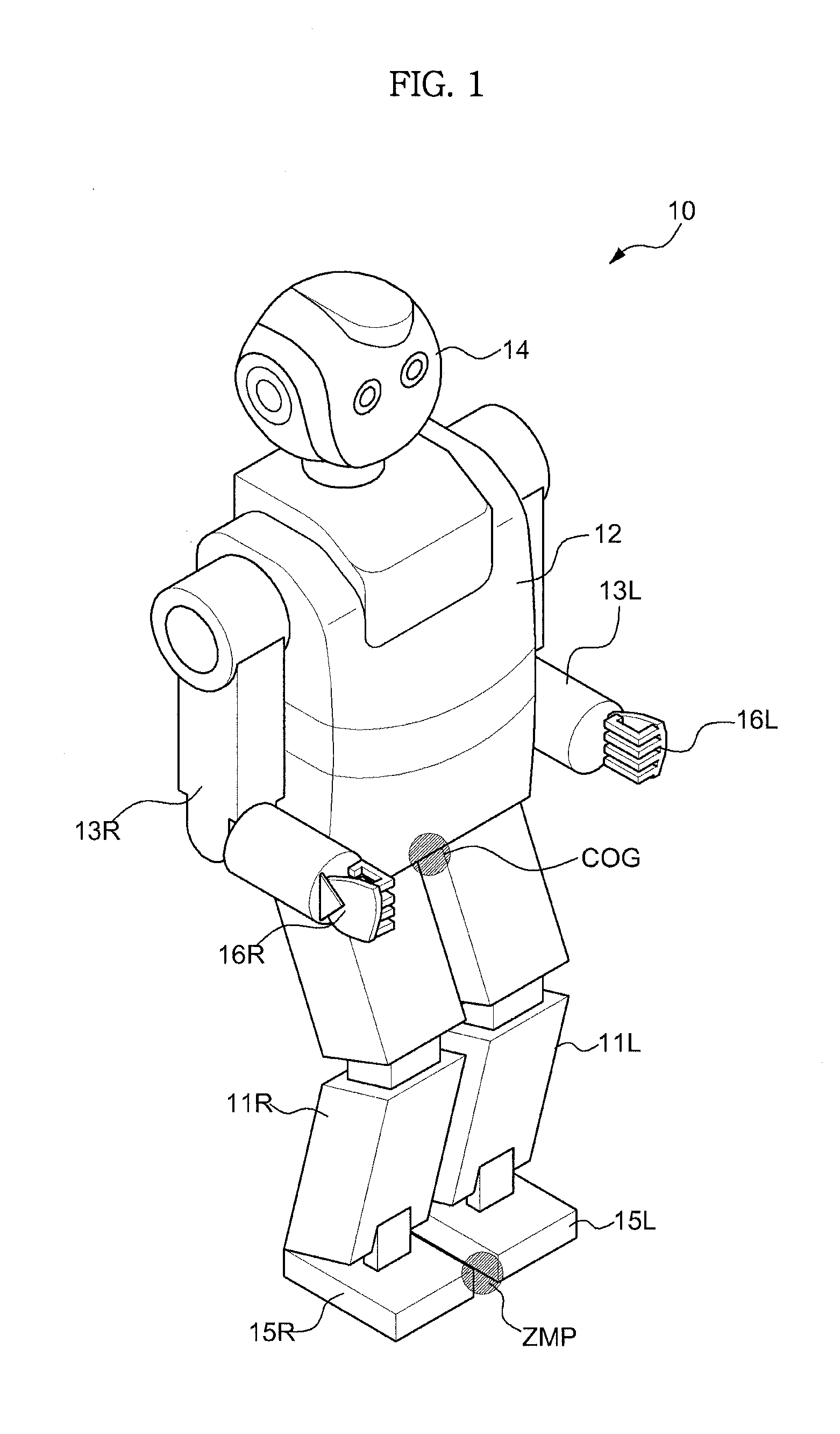
[0040]FIG. 1 is a view showing the appearance of a legged mobile robot according to example embodiments.

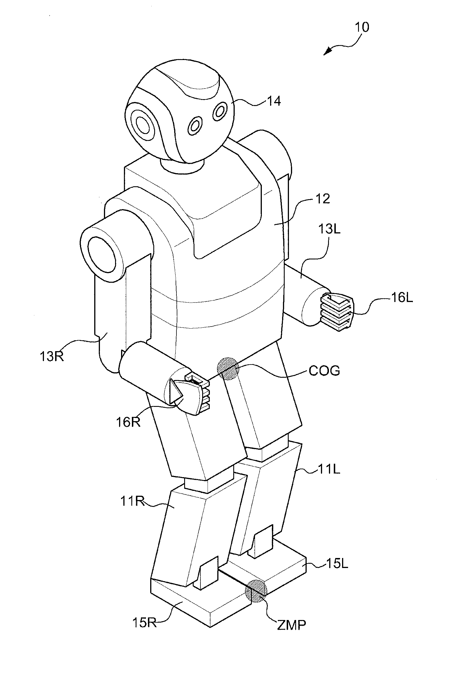
[0041]As shown in FIG. 1, the robot 10 is a bipedal robot which walks erect using two legs 11R and 11L similar to a human, and includes a trunk 12, two arms 13R and 13L and a head 14 mounted on an upper side of the trunk 12. The robot 10 further may include feet 15R and 15L and hands 16R and 16L respectively mounted on the front ends of the two legs 11R and 11L and the arms 13R and 13L. Regarding the reference numerals, R and L respectively denote right and left, COG denotes the center of gravity of the robot 10, ZMP denotes a point where moments of a roll axis direction (x-axis direction which is the traveling direction of the robot) and a pitch axis direction (y-axis direction which is the lef...


PUM


Abstract

Disclosed is an apparatus and method adjusting motion of each joint of a robot to compensate for friction force of each joint such that the sole of the foot of the robot clings to the ground. The motion of each joint is adjusted as if gravity acts on each joint of the robot in a direction opposite to gravity and the robot is held in an erect state. Therefore, the robot can stand while keeping its balance without falling.

Description

CROSS-REFERENCE TO RELATED APPLICATIONS[0001]This application claims the benefit of Korean Patent Application No. 2009-0074986, filed on Aug. 14, 2009 in the Korean Intellectual Property Office, the disclosure of which is incorporated herein by reference.BACKGROUND[0002]1. Field[0003]Example embodiments relate to an apparatus and method controlling a legged mobile robot, which may balance the legged mobile robot to prevent falling.[0004]2. Description of the Related Art[0005]Recently, research into a robot which walks erect has been actively conducted.[0006]If there is an inclined surface, such as stairs or a rough plane, or an obstacle when a robot walks, a legged robot has greater mobility than a wheeled robot. In particular, since the legged robot may lose its balance and fall, stability is taken into consideration when the walking pattern of the robot is set.[0007]In order to guarantee the dynamic stability of a legged robot, research into generation of a walking pattern in cons...

Claims


Application Information

Patent Timeline
Patent Type & Authority Applications(United States)
IPC IPC(8): B25J9/00
CPCB62D57/032B25J5/00B25J9/0006B25J9/16B25J9/1641B25J13/00B25J17/00
Inventor KIM, JOO HYUNGROH, KYUNG SHIKKWON, WOONGHAN, JEONG HEONPARK, JAE HOKWAK, HO SEONG
Owner SAMSUNG ELECTRONICS CO LTD
Learn More