
Crack resistant coating and method of applying crack resistant coating

Inactive Publication Date: 2011-02-17
ARR MAZ PRODS
View PDF10 Cites 12 Cited by
  • Summary
  • Abstract
  • Description
  • Claims
  • Application Information

AI Technical Summary

Benefits of technology

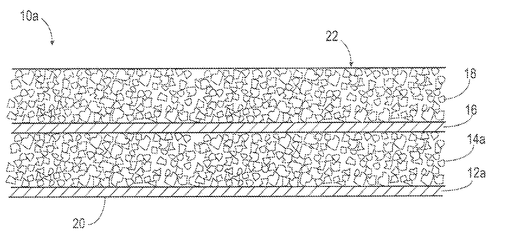
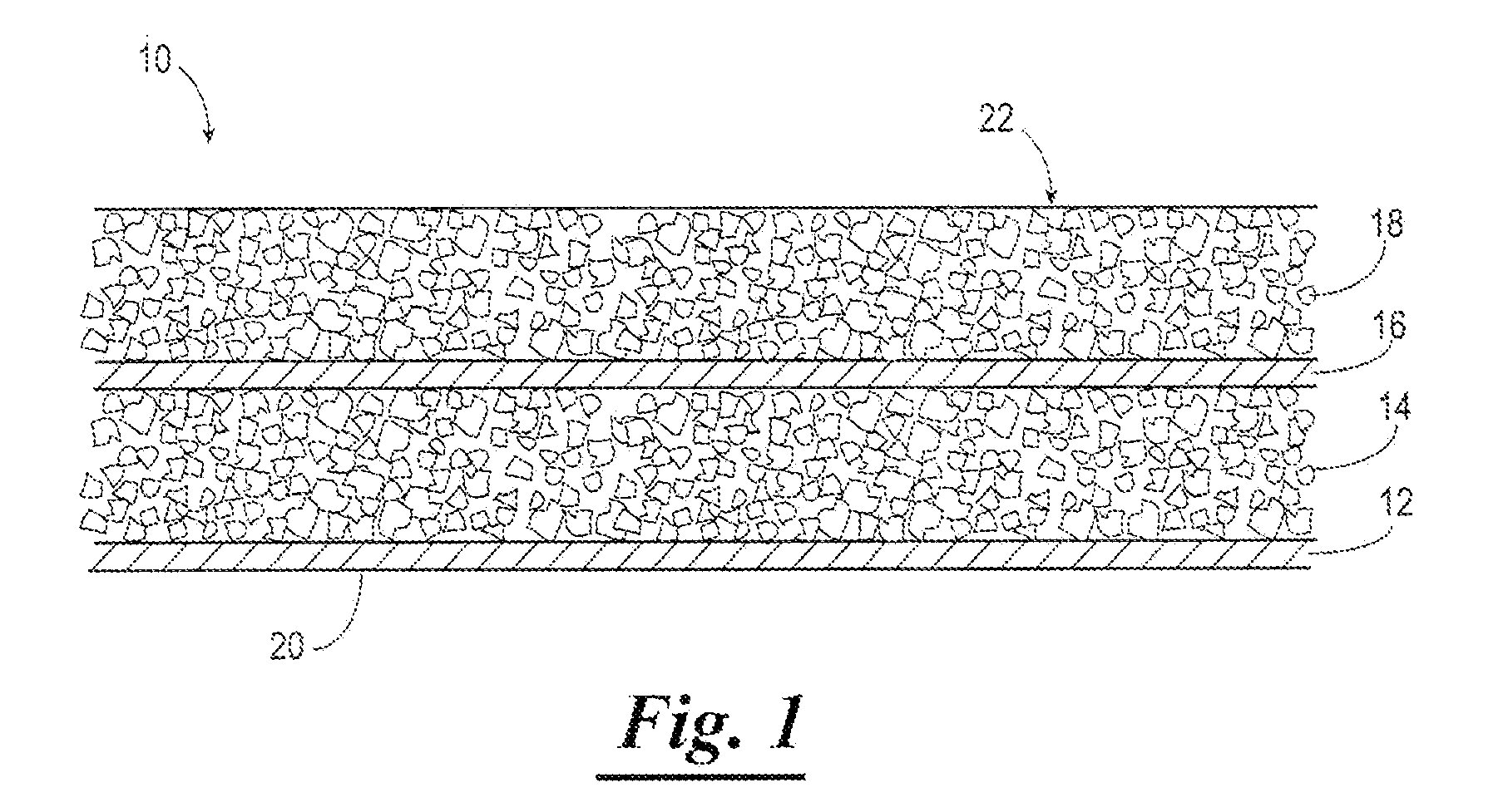
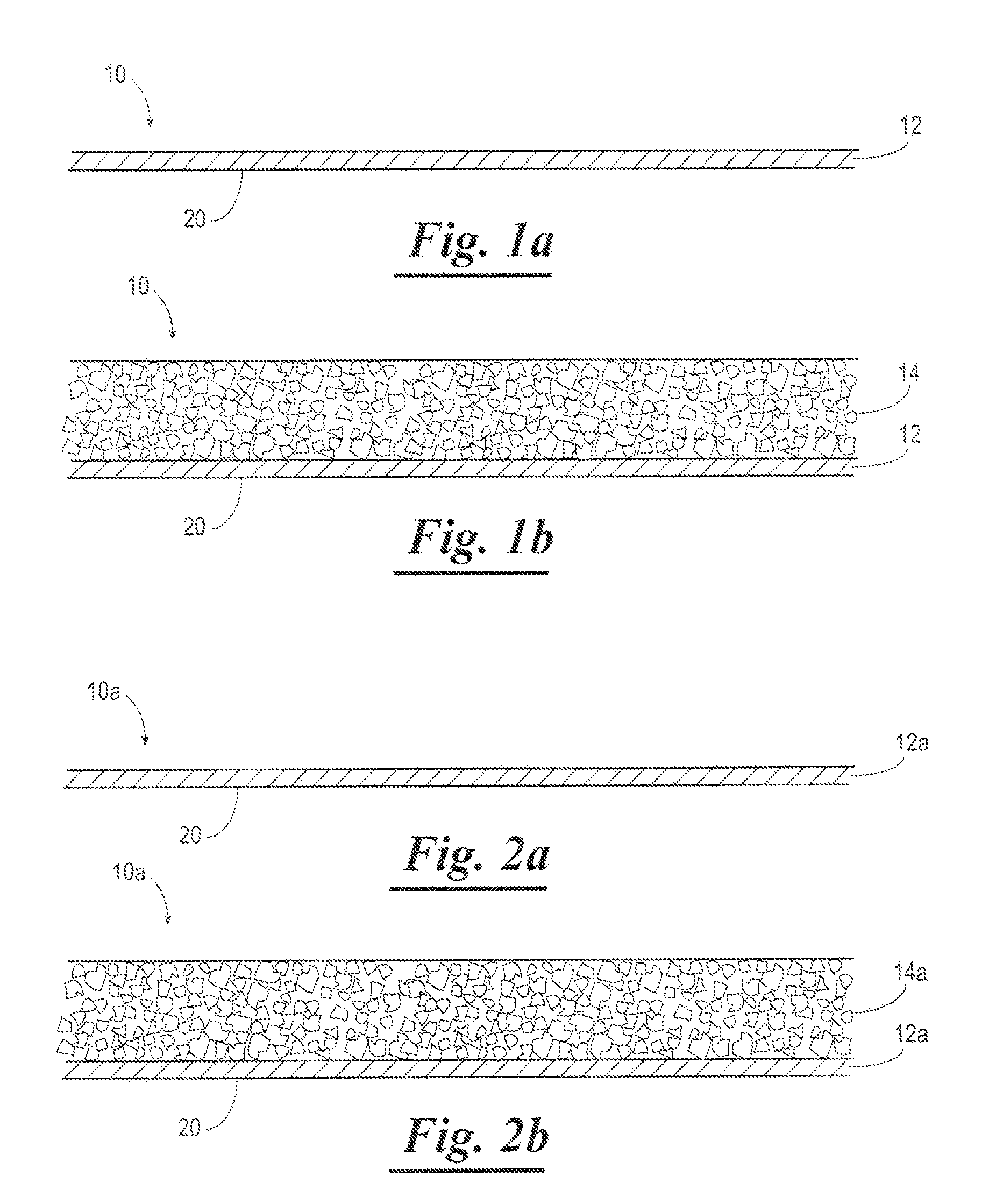
[0017]The method may further comprise the step of compacting the first aggregate mixture layer against the first binding material layer prior to the step of applying the second binding material layer, where the step of compacting the first aggregate mixture layer against the first binding material layer provides a substantially uniform thickness of the first aggregate mixture layer and the first binding material layer, reduces air void space in the first aggregate mixture layer, and promotes adhesion of the first aggregate mixture layer to the first binding material layer. The method may further comprise the step of compacting the second aggregate mixture layer against the second binding material layer to provide a substantially uniform thickness of the crack resistant coating, where the step of compacting the second aggregate mixture layer against the second binding material layer also reduces air void space in the second aggregate mixture layer, promotes adhesion of the second binding material layer to the first aggregate mixture layer, and promotes adhesion of the second aggregate mixture layer to the second binding material layer.

Problems solved by technology

Cracks in the pavement are a form of distress, which can lead to premature failure of the new pavement.
The cracks allow moisture (i.e. water) to enter into the existing (i.e. underlying) pavement and create structural support issues.
Additionally, the cracks can also create ride quality issues, which may require grinding to smoothing, time intensive crack filing operations to seal the pavement, or significant costs to apply one or more additional pavement layers to address the problem.
It is common for pavements to crack during their expected service life.
Reflective cracks occur when a pavement layer is placed over a cracked pavement.
The existing cracks transmit into the new pavement after a period of time.
The pavement cracks form when asphalt in the pavement hardens from aging to the point that it cannot relieve the stress as the pavement tries to bend from the differences in temperature from the top of the pavement to the bottom of the pavement.
Thermal cracks normally manifest as cracks that run transverse to the direction of travel.
Heavy truck loading also causes cracks in the pavement.
This tensile force can create a longitudinal crack where the outer edge of the radial tires contacts the pavement.
Construction issues may also contribute to longitudinal cracking.
Segregation of a pavement mixture may occur from mechanical issues with the paving equipment.
This is an inefficient solution to the problem because of the increased cost and time to lay the paving mixture in amounts that large.
This technique is limited by the amount of liquid binding material that may be applied without creating flow of the liquid binding material to areas other than intended.
If opened to traffic before a suitable paving mixture is placed over the interlayer, the interlayer may create high traffic noise and hazards from loose aggregate.
The grids or fabrics are challenging to place smoothly, especially when paving is not in a straight line.
In addition, grids and fabrics are extremely expensive and are relatively slow to construct.
High asphalt content pavement poses the problem of the liquid binding material flowing from the mixture during manufacture or placement.
High asphalt content interlayer mixtures may be sensitive to deformation from traffic and may provide low texture or reduced safety for the motoring public.
One problem with the pavement disclosed in the Bense et al. patent is that the pavement readily cracks in less than about one (1) year, more specifically, the pavement typically demonstrates substantial reflective cracking in less than 6 months.

Method used


Image

  • Crack resistant coating and method of applying crack resistant coating
  • Crack resistant coating and method of applying crack resistant coating
  • Crack resistant coating and method of applying crack resistant coating

Examples


example 1

[0075]A test trial was executed in Missouri on Route T about 5.6 Km West of Route 100. A dense graded (<10% air voids) aggregate mixture was produced using aggregate particles and asphalt solution. The aggregate mixture utilized 4.8% asphalt solution by weight and exhibited 5.0% air voids. All Crack Resistant Layers were applied at about 4.44 cm thick. Prior to experimentation, the road was surveyed for cracks and it exhibited an uneven crack pattern, Table #1 shows the data from the test site.

TABLE #1Field ExperimentSt Albens Road, Route T Missouri - 5.6 Km West of Rte 1005% air voids, 4.8% binder content, 4.44 cm thick thickEmulsified BindingEmulsionBonding LayerExisting CracksLayer (L / m2)ResidueL / m2per 1000 m (m)0.36132%0.1169350.67862%0.42012350.84062%0.521937

[0076]Table #2 shows the calculated results from the trials and crack count data after 9 months of service. The data shows the control section with 0% AVFA, 0.00 cm in height of Substantially Voidiess layer and a Total Bind...

example 2

[0078]A second field trail was conducted on private property with an open graded aggregate mixture. In normal application, an aggregate mixture with >10% air voids is considered open graded and has little to no resistance to cracking. The first section was produced with one binding material layer and one aggregate mixture layer. The second experimental section was produced utilizing a binding material and aggregate mixture followed by a successive application of another binding material and aggregate mixture. All binding materials were the same as well as all aggregate mixtures were identical.

TABLE #3Field Data - 18 months oldTulsa Field Trial10.0% air voids, 5.25% binder contentEmulsified BindingEmulsionBonding LayerMixtureLayer (L / m2)ResidueL / m2Depth (cm)1.08462%0.6722.222.53062%1.5693.49

[0079]Table #3 details the application data. Both experimental sections utilized high rates of binding material.

TABLE #4Calculations and ResultsTulsa Field TrialVoidlessTotal BindingFilledMaterial...


PUM

PropertyMeasurementUnit
Fractionaaaaaaaaaa
Fractionaaaaaaaaaa
Timeaaaaaaaaaa

Abstract

The present invention relates to a method for applying a crack resistant coating on a surface, where the crack resistant coating increases resistance to high vertical and horizontal movements and high shear stresses on the surface. The method comprises the steps of applying a binding material to the surface and applying an aggregate mixture within 15 seconds of applying the binding material to the surface, where the aggregate mixture comprises aggregate particles and an asphalt solution and where the aggregate mixture has a plurality of air voids, and where the binding material fills at least 15% of the air voids in the aggregate mixture (AVFA).

Description

BACKGROUND OF THE INVENTION[0001]1. Field of the Invention[0002]The present invention relates to a surface coating applied to a surface, and more particularly, not by way of limitation, to a crack resistant coating on a surface and a method for applying the crack resistant coating on the surface to increase resistance to high vertical and horizontal movements and high shear stresses caused by cracks or irregularities in the surface and high shear stresses caused by traffic. In addition, the crack resistant coating of the present invention provides increased resistance to reflective cracking.[0003]2. Description of the Related Art[0004]It is desirable to place a new surface or a new pavement over pavement used to construct roads, parking lots, airport runways, airport taxiways, and the like and not have existing cracks reappear in the new pavement for long periods of time. Cracks in the pavement are a form of distress, which can lead to premature failure of the new pavement. The crac...

Claims


Application Information

Patent Timeline
IPC IPC(8): E01C7/00E01C19/00
CPCC08L95/00C09D195/00Y10T428/26E01C7/187E01C7/185Y10T428/31815Y10T428/249983Y10T428/249982Y10T428/249955
Inventor EXLINE, MARVIN KELLERWINGO, JON BRETTCUNNINGHAM, JR., JAMES JOSEPHBARNAT, JAMES J.
Owner ARR MAZ PRODS
Learn More