
Method and Apparatus for Providing Energy to Passive Tags in a Radio-frequency Identification System

a radio-frequency identification system and energy supply technology, applied in the field of radio-frequency identification (rfid) technology, can solve the problems of limiting many applications of such radio-frequency identification systems, tags may not have enough energy to perform reliable writing operations, etc., to achieve the effect of improving the reliability of executing the reading, extending the read-only and/or rewritable range of the radio-frequency identification system, and more energy

Inactive Publication Date: 2011-02-17
SIEMENS AG
View PDF7 Cites 10 Cited by
  • Summary
  • Abstract
  • Description
  • Claims
  • Application Information

AI Technical Summary

Benefits of technology

"The present invention provides a method, apparatus, and system for improving the energy supply to passive tags in a radio-frequency identification system. This is achieved by selecting at least one period during the communication process of the reader / writer as an enhanced period, where the tag can obtain more energy from continuous waves. The enhanced period can be adjusted based on the received signal strength or the bit number to be written to the tag. This method improves the reliability of the system and allows for a larger read-only and rewriting range. The invention also includes a reader / writer apparatus and an independent energy supplying apparatus for achieving this method."

Problems solved by technology

Consequently, these tags may not have enough energy to perform the reliable writing operation after having executed a reading operation.
This will limit many applications of such radio-frequency identification systems.

Method used


Image

  • Method and Apparatus for Providing Energy to Passive Tags in a Radio-frequency Identification System
  • Method and Apparatus for Providing Energy to Passive Tags in a Radio-frequency Identification System
  • Method and Apparatus for Providing Energy to Passive Tags in a Radio-frequency Identification System

Examples


Embodiment Construction

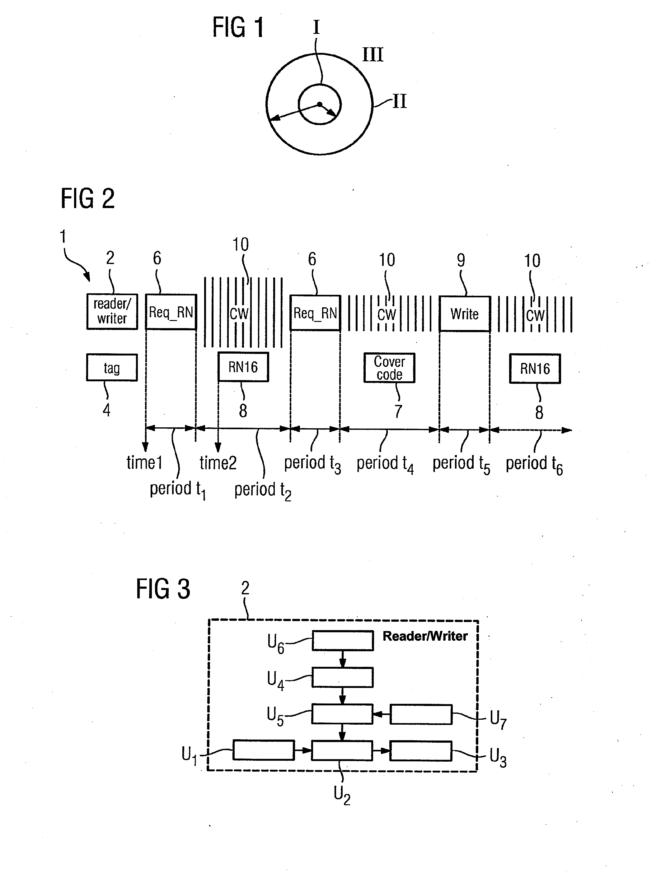
[0041]FIG. 1 is an illustration of read / write ranges, whereas the inner circle represents a rewritable range I, the outer circle presents a read-only range II and the area around the circles represents an unreadable range III.

[0042]In accordance with the present invention, by way of the embodiments described below, energy is provided to passive tags in a radio-frequency identification system 1 using such passive tags 4 (hereinafter referred to as tags), so that the tags 4 obtain more energy for performing the reading and / or writing operations reliably. From the point of view of a radio-frequency identification system 1, this means an extended coverage range.

[0043]In a first embodiment of the present invention the energy supply to the tags is increased by increasing the power strength in transmitting the continuous waves by a reader / writer.

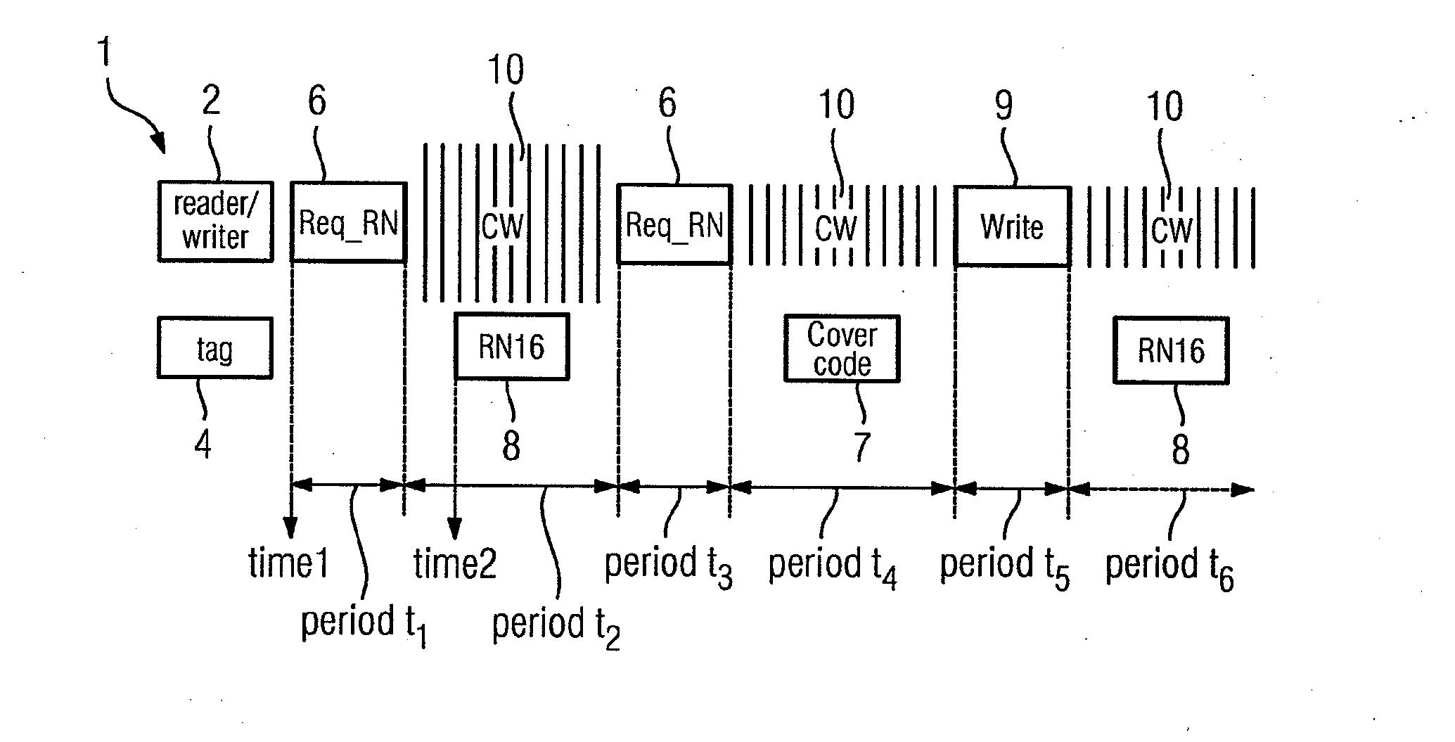
[0044]FIG. 2 is an illustration of an exemplary process in which the reader / writer 2 performs a writing operation to a tag 4 after having performe...


PUM


Abstract

A method and an apparatus for providing energy to passive tags in a radio-frequency identification system in which a radio-frequency identification system uses the passive tags, a reader / writer sends commands and continuous waves alternately during a communication process, and the tags can obtain energy from these signals sent by the reader / writer, wherein at least one period is selected from those periods for transmitting the continuous waves, and for the continuous wave transmitting signals during this period, an enhanced transmitting power is used, or a extended transmitting time is used, or during this period continuous waves are sent additionally to the passive tags by an independent energy supplying apparatus provided separately, so that the passive tags can obtain from the continuous waves during the selected period more energy for reading and / or writing, thereby improving the reliability of the reading and / or writing operations, and increasing the rewritable range of the radio-frequency identification system.

Description

CROSS-REFERENCE TO RELATED APPLICATIONS[0001]This is a U.S. national stage of International Application No. PCT / EP2009 / 050944, filed on 28 Jan. 2009. Priority is claimed on Chinese Application No. 200810004983.0, filed on 31 Jan. 2008. The entire content of both applications are incorporated herein by reference.BACKGROUND OF THE INVENTION[0002]1. Field of the Invention[0003]The present invention relates to a radio-frequency identification (RFID) technology and, more particularly to a method and an apparatus for providing energy to passive tags in a radio-frequency identification system using such passive tags.[0004]2. Description of the Related Art[0005]Typically, a radio-frequency identification system comprises a reader / writer (or interrogator) and the tags. In a radio-frequency identification system using passive tags, the energy of the passive tags is obtained from the radio frequency waves sent by the reader / writer. For example, in the radio-frequency identification system base...

Claims


Application Information

Patent Timeline
Patent Type & Authority Applications(United States)
IPC IPC(8): G06K7/01
CPCG06K7/0008G06K19/0712G06K19/0707G06K7/10217
Inventor HORST, DIETERLAMPE, MATTHIASYU, DANYUAN, YONG
Owner SIEMENS AG
Learn More