
Adaptive Control Ducted Compound Wind Turbine

a compound wind turbine and adaptive control technology, which is applied in the direction of combination engines, electric generator control, machines/engines, etc., can solve the problems of large exit to inlet (or nozzle to exit) diffuser ratio, adversely affecting rotor/propeller performance, and harming efficiency

Inactive Publication Date: 2011-02-17
SAMMY JOHANN QUINCY
View PDF74 Cites 31 Cited by
  • Summary
  • Abstract
  • Description
  • Claims
  • Application Information

AI Technical Summary

Problems solved by technology

A problem common to diffuser type shrouds is flow separation from the shroud inner surface walls which negates the benefit of the diffuser shroud and causes pressure rise which may adversely affect rotor / propeller performance and thus harm efficiencies.
Further, problems and complications of the diffuser design (DAWT) is the large exit to inlet (or nozzle to exit) diffuser ratios required, to form lower pressure gradients at exit.
Additionally, low aspect ratio ducts, shrouds and diffuser in relation to the nozzle and exit area has led to problems with buffeting, yaw control due to air entrainment and high drag systems inherent in the design (higher pressure).
Turbulent flow fields are also generated at the exit ducts of DAWTS, leading to efficiency and performance losses due to the increased diameter of irrotational and expanding wake flow.
All prior art of ducted (concentrator type) / diffuser augmented wind turbines (DAWTS) still do not address the problem of expanding irrotational wake flow that can disrupt flow and wind supply in a wind turbine array and lead to lower overall performance and degradation of efficiency of proximate wind turbines sited in wind farms because of turbulent flow.
Furthermore, ducted / shrouded turbines of the prior art are prone to ice formation in freezing conditions due to the increase in wetted area of the duct.
Ice-build up causes gross inefficiency and performance losses as the result of flow separation, blockage and change of surface geometry from ice accumulation.
Further loss of efficiencies lowering coefficient of performance in wind turbines un-ducted / ducted is due but not limited to propeller, generator, gearbox, and transmission inefficiencies, and poor yawing reaction control—a function of unsteady aerodynamics in wind turbines.

Method used


Image

  • Adaptive Control Ducted Compound Wind Turbine
  • Adaptive Control Ducted Compound Wind Turbine
  • Adaptive Control Ducted Compound Wind Turbine

Examples


Embodiment Construction

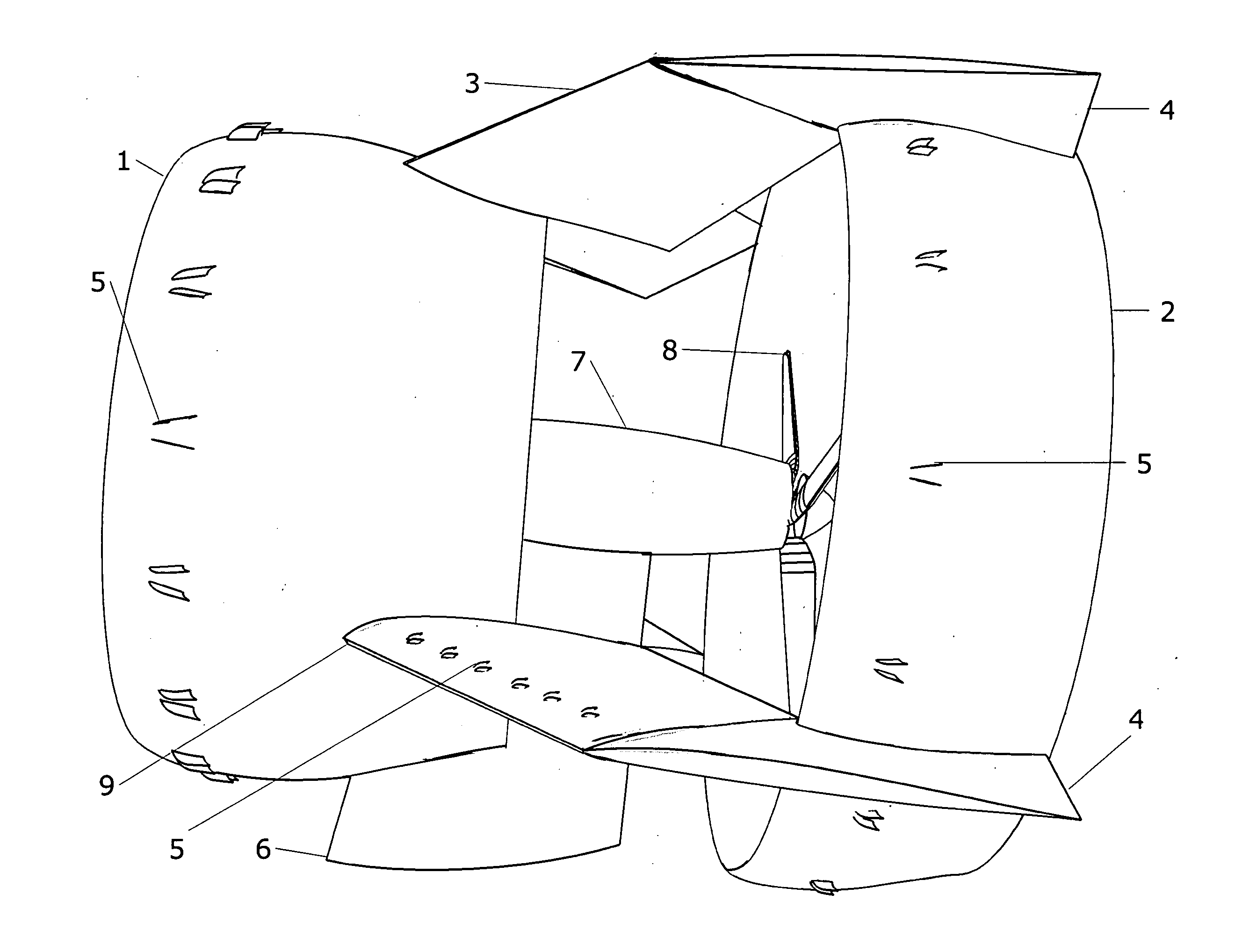
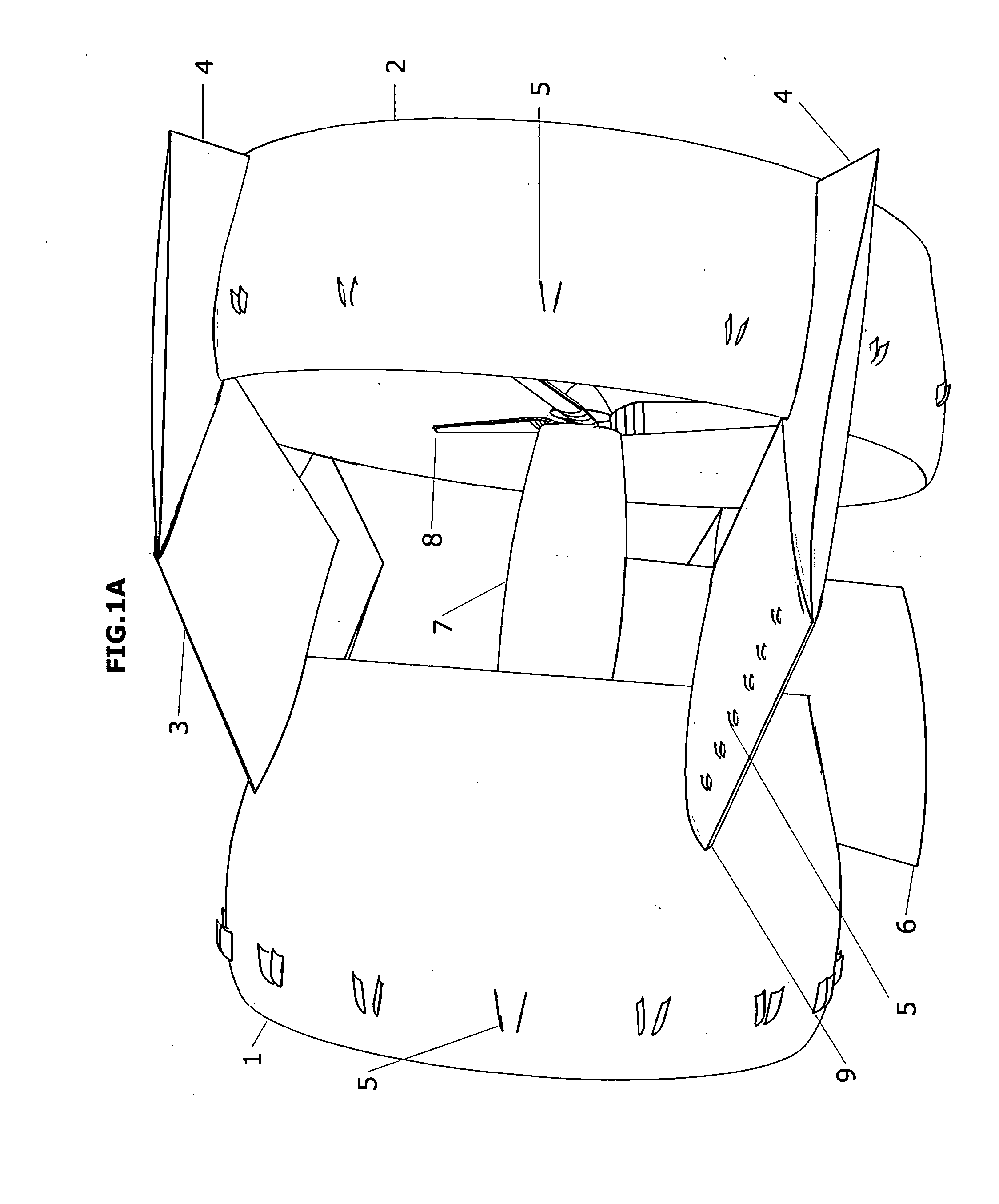
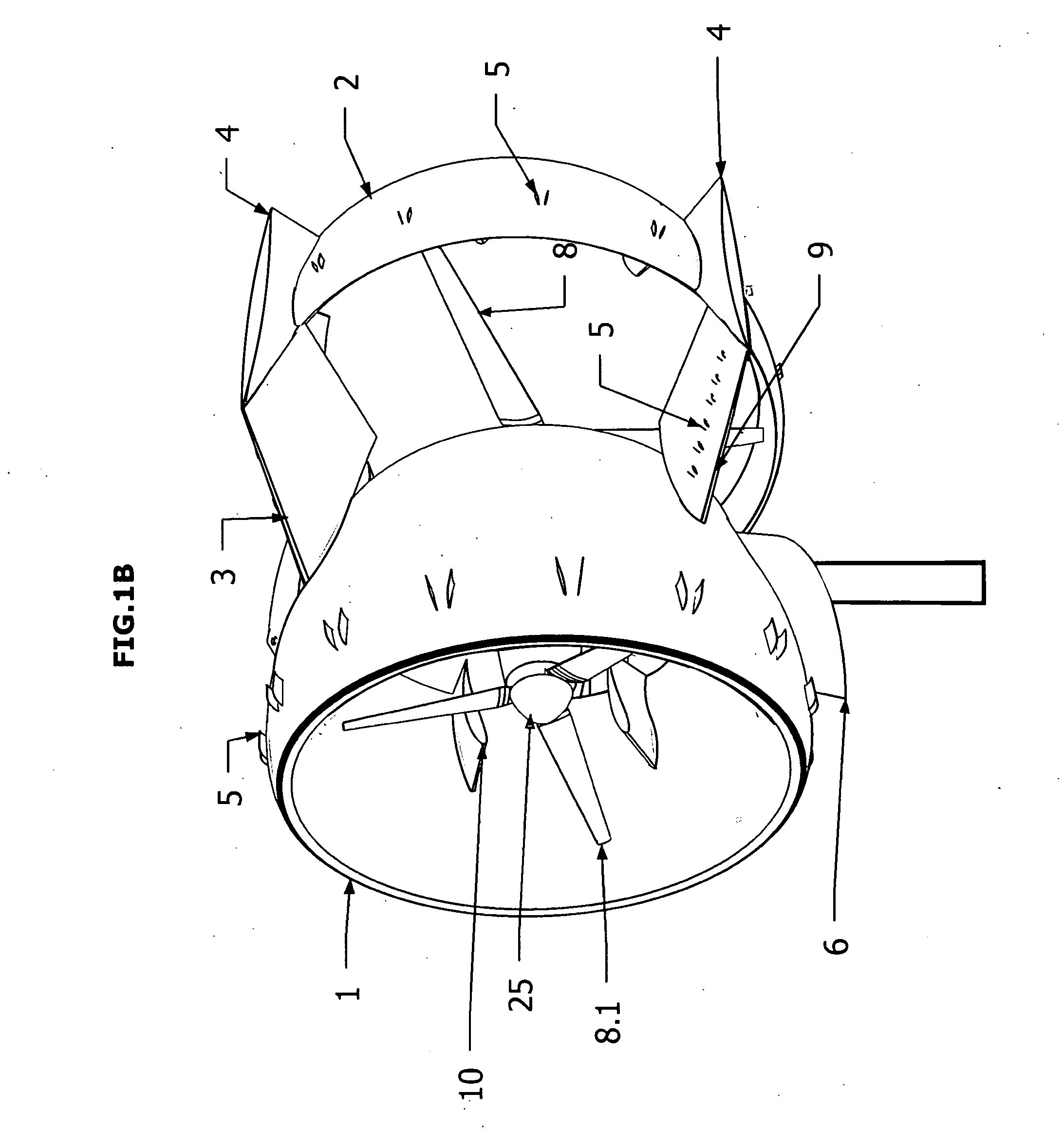
[0020]Embodiments of the present invention provide for a compound, dual annulus / annular wing, counter rotating propeller blades, dual rotor / turbine system, consisting of variable and / or fixed vanes on the inner walls, horizontal and vertical stabilizers connecting the forward and after ducts, and vortex generators for flow attachment along the inner / outer duct walls circumferentially arranged for efficient harvesting of wind energy. The performance of rotors / propellers / fans within a shroud or duct improve turbine efficiency by minimizing losses at the rotor / propeller tip, provided suitable clearance between the propeller tip and shroud are met in these axial flow systems.

[0021]Ducted propellers / ducted fans provide high static thrust per rotor diameter than an un-ducted propeller. Un-ducted, mono-propeller HAWT turbines deflect away a significant portion of the incoming free-stream resulting in lower turbine efficiency and power production and vortex shedding also creates turbulence ...


PUM


Abstract

A high efficiency, adaptive control, compound ducted wind turbine capable of providing higher efficiency in energy extraction from a fluid. Performance of efficiency expressed as coefficient of performance (Cp) in accordance with the Lanchester-Betz-Joukowski limits is sustainable and significantly higher than an un-ducted, mono-propeller wind turbine of comparable diameter.

Description

RELATED APPLICATIONS[0001]This application is related to provisional application serial number 61219347, “High Efficiency Ducted, Compound Rotor Turbine”, Sammy, filed on Jun. 22, 2009 and claims priority therefrom.BACKGROUND[0002]1. Field[0003]This disclosure relates to wind turbines and wind collectors for horizontal axis wind turbines (HAWT) that are designed to harvest energy from the wind and transmit electrical energy to power storage or sent directly to end user for immediate energy consumption (grid-tied). More particularly, the present disclosure describes a compound rotor wind turbine that is enclosed within two separate annulus (annular wings) to provide for higher efficiencies in wind energy extraction based on coefficient of performance derived from the Lanchester-Betz-Joukowski limit.[0004]2. Description of Related Art[0005]Horizontal Axis Wind Turbines (HAWT) has been largely dominated by un-ducted / shrouded, mono-propeller turbine(s) as the primary configuration for w...

Claims


Application Information

Patent Timeline
Patent Type & Authority Applications(United States)
IPC IPC(8): F03D9/00
CPCF03D1/025F03D1/04Y02E10/726F05B2250/323F05B2240/122F03D9/25F03D15/10Y02E10/72
Inventor SAMMY, JOHANN QUINCY
Owner SAMMY JOHANN QUINCY
Learn More