
Motion control device for vehicle

Inactive Publication Date: 2011-02-10
ADVICS CO LTD
View PDF28 Cites 18 Cited by
  • Summary
  • Abstract
  • Description
  • Claims
  • Application Information

AI Technical Summary

Benefits of technology

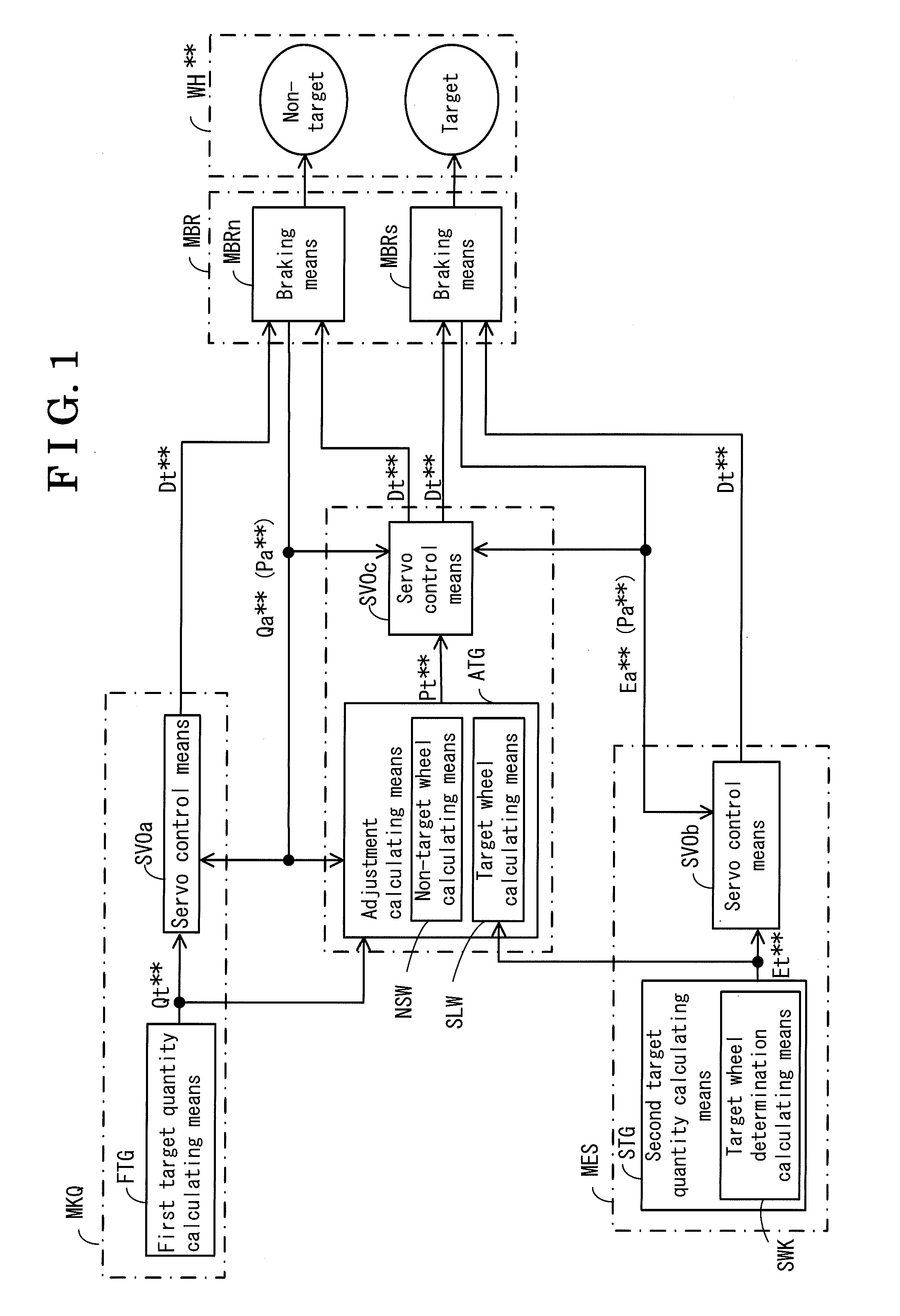
[0010]According to an aspect of the present invention, a motion control device for a vehicle includes a braking means for applying a brake torque to each of a plurality of wheels of the vehicle, an avoidance control means for calculating a first target quantity, which is used for an avoidance control for applying the brake torque to each of the plurality of the wheels via the braking means in order to avoid an emergency state of the vehicle, a stabilization control means for determining a target wheel out of the plurality of the wheels as a target of a supply of the brake torque and calculating a second target quantity used for a stabilization control for applying the brake torque to the target wheel via the braking means in order to ensure a stability of the vehicle, and a brake control means for controlling the brake torque to be applied to a non-target wheel, which differs from the target wheel, on the basis of the first target quantity and controlling the brake torque to be applied to the target wheel on the basis of the first target quantity and the second target quantity.
[0011]According to a further aspect of the present invention, a motion control device for a vehicle includes a braking means for applying a brake torque to each of a plurality of wheels of the vehicle, an avoidance control means for calculating a first target quantity and a first actual quantity, which are used for an avoidance control for applying the brake torque to each of the plurality of the wheels via the braking means in order to avoid an emergency state of the vehicle, a stabilization control means for determining a target wheel out of the plurality of the wheels as a target of a supply of the brake torque and calculating a second target quantity used for a stabilization control for applying the brake torque to the target wheel via the braking means in order to ensure a s

Problems solved by technology

As a result, the understeering tendency of the vehicle is not resolved, because the understeering restriction control is not executed.
As a result, a sudden change may occur at a total wheel braking force when the control is switched.
In this case, a driver may feel discomfort.

Method used


Image

  • Motion control device for vehicle
  • Motion control device for vehicle
  • Motion control device for vehicle

Examples


first embodiment

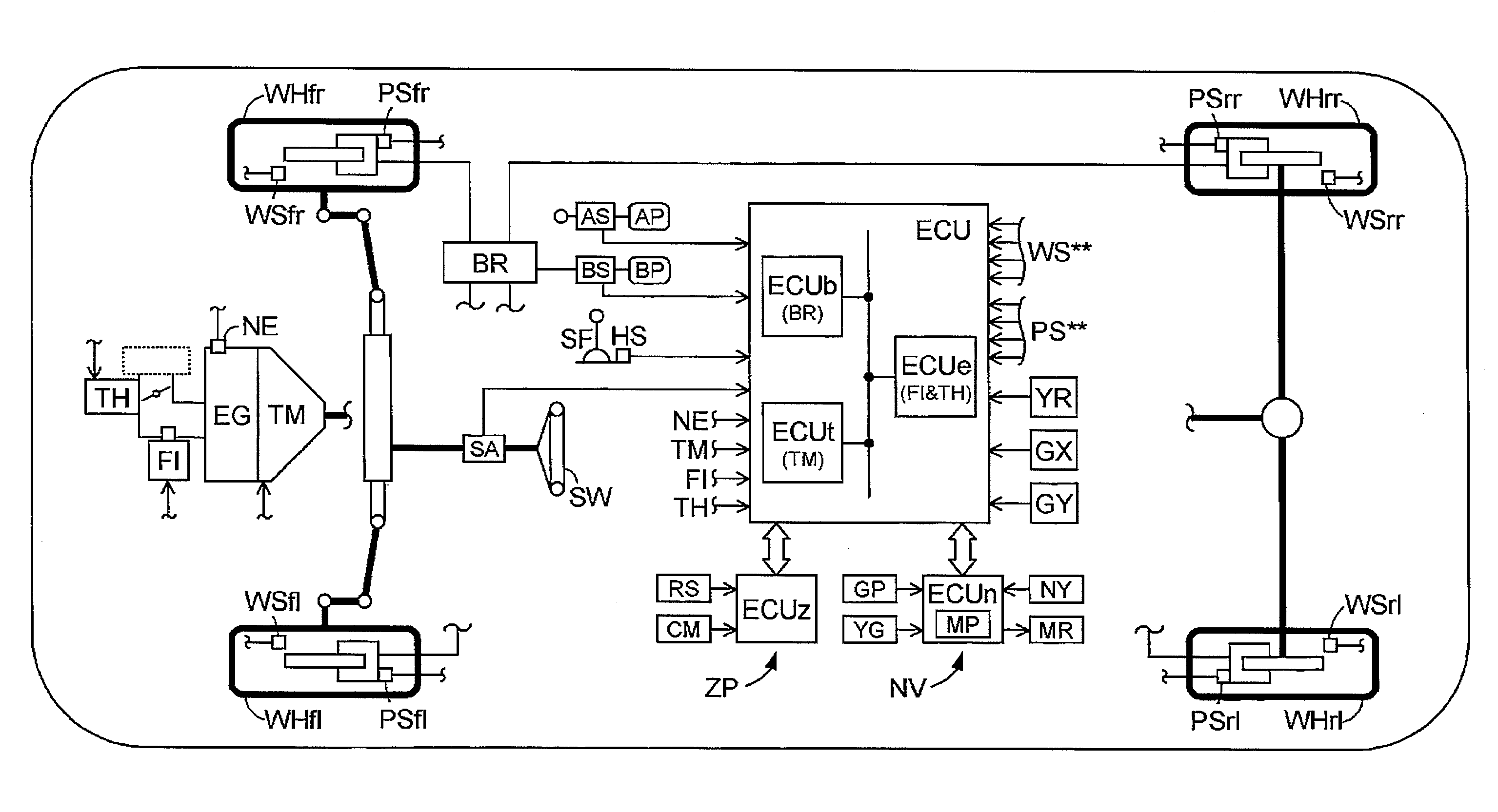
[0025]Illustrated in FIG. 1 is an entire configuration of a motion control device (which will be hereinafter referred to simply as a device) according to a first embodiment. The device includes a braking means MRB, an avoidance control means MKQ, a stabilization control means MES, and a brake control means MBC.

[0026]Each wheel WH** includes a known wheel cylinder WC**, a known brake caliper BC**, a known brake pad PD** and a known brake rotor RT** as the braking means MBR. A brake torque is applied to each wheel WH** in a manner where the brake pad PD** is pressed against the brake rotor RT** when a brake hydraulic pressure is applied to the wheel cylinder WC**, which is provided at the brake caliper BC**, so that a friction force generated when the brake pad PD** is pressed against brake rotor RT** acts on the wheel WH** as the brake torque. The braking means MBR includes hydraulic pressure pumps OP1 and OP2, and electromagnetic valves SS**, SZ** and SG** for controlling the brake ...

second embodiment

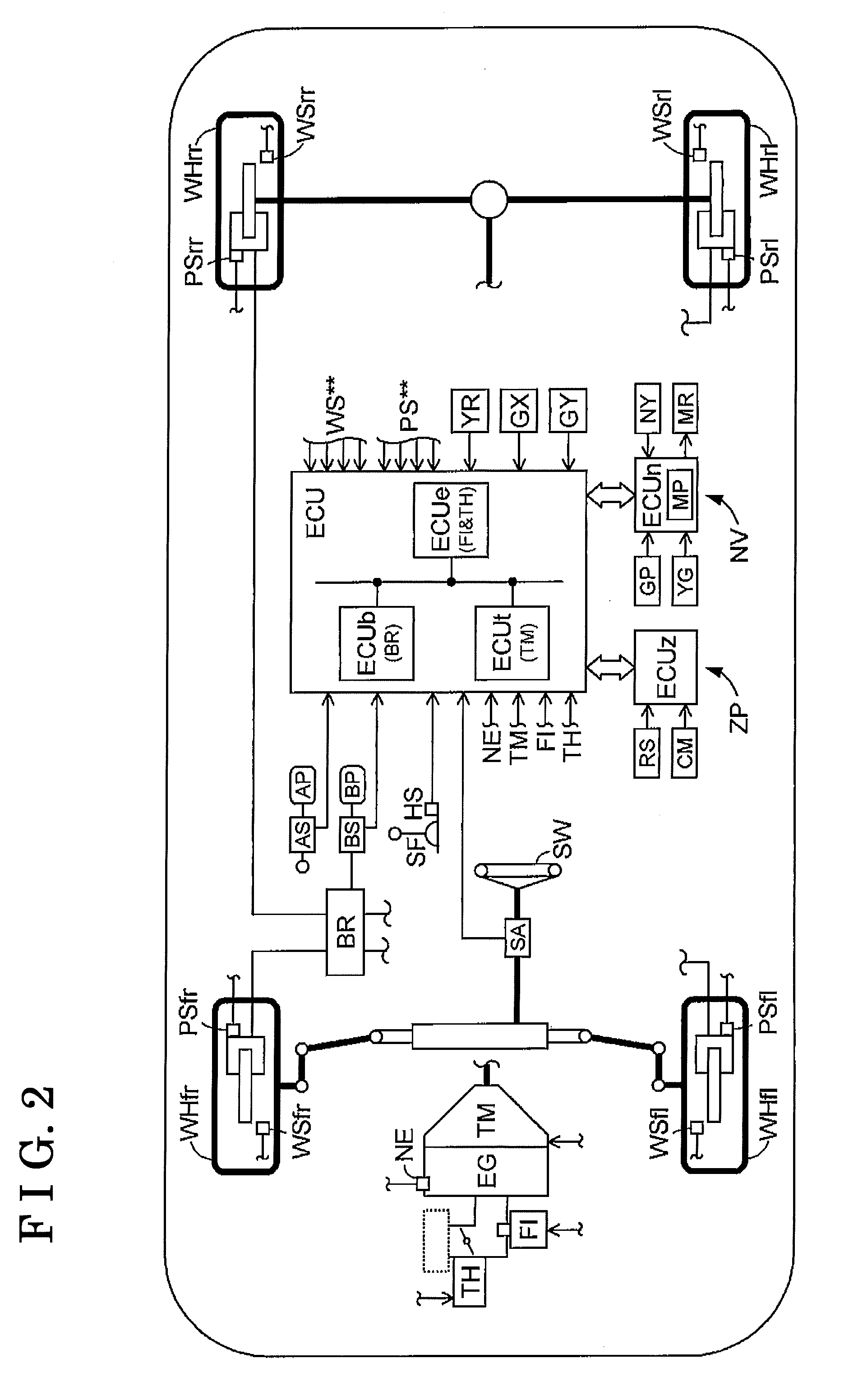
[0079]A second embodiment of a motion control device for a vehicle (which will be hereinafter referred to simply as a device) will be described below with reference to the attached drawings. In the second embodiment, means and functional blocks having the same or similar function and configuration as the corresponding means and functional blocks of the device according to the first embodiment are indicated by the identical reference numerals. Illustrated in FIG. 6 is an entire configuration of the device according to the second embodiment. As illustrated in FIG. 6, the device includes a braking means MBR, an avoidance control means MKQ, a stabilization control means MES, a wheel speed obtaining means MWS and a brake control means MBC.

[0080]Symbols “**” are used to comprehensively indicate wheels. For example, “fl” indicates a front-left wheel, “fr” indicates a front-right wheel, “rl” indicates a rear-left wheel and “rr” indicates a rear-right wheel. Reference alphabets in brackets “...


PUM


Abstract

A motion control device for a vehicle includes a braking means for applying a brake torque to each of a plurality of wheels of the vehicle, an avoidance control means for calculating a first target quantity, used for an avoidance control for applying the brake torque to each wheel via the braking means in order to avoid an emergency state of the vehicle, a stabilization control means for determining a target wheel, to which the brake torque is applied, out of the wheels and calculating a second target quantity used for a stabilization control for applying the brake torque to the target wheel in order to ensure a vehicle stability, and a brake control means for controlling the brake torque applied to a non-target wheel based on the first target quantity and controlling the brake torque applied to the target wheel based on the first and second target quantities.

Description

CROSS REFERENCE TO RELATED APPLICATIONS[0001]This application is based on and claims priority under 35 U.S.C. §119 to Japanese Patent Application 2009-182826, filed on Aug. 5, 2009, Japanese Patent Application 2009-182864, filed on Aug. 5, 2009, the entire contents of which are incorporated herein by reference.FIELD OF THE INVENTION[0002]The present invention generally relates to a motion control device for a vehicle.BACKGROUND[0003]Disclosed in JP2004-259151A is a collision avoidance control system for a vehicle, which executes a collision avoidance control for avoiding a collision of the vehicle against a target object while accurately determining a possibility of the collision and calculating a control amount for avoiding the collision with less calculation in a manner where the collision avoidance control system selects the target object (e.g. a vehicle traveling ahead of the subject vehicle having the collision avoidance control system) to be subjected to the control on the bas...

Claims


Application Information

Patent Timeline
IPC IPC(8): G06F19/00
CPCB60T8/17558B60T8/17551B60T8/885
Inventor YASUI, YOSHIYUKI
Owner ADVICS CO LTD
Learn More