
In-home System Monitoring Method and System

a monitoring method and system technology, applied in the field of data communication, can solve problems such as personal computers

Active Publication Date: 2011-02-03
PINO JR ANGELO J +1
View PDF6 Cites 141 Cited by
  • Summary
  • Abstract
  • Description
  • Claims
  • Application Information

AI Technical Summary

Benefits of technology

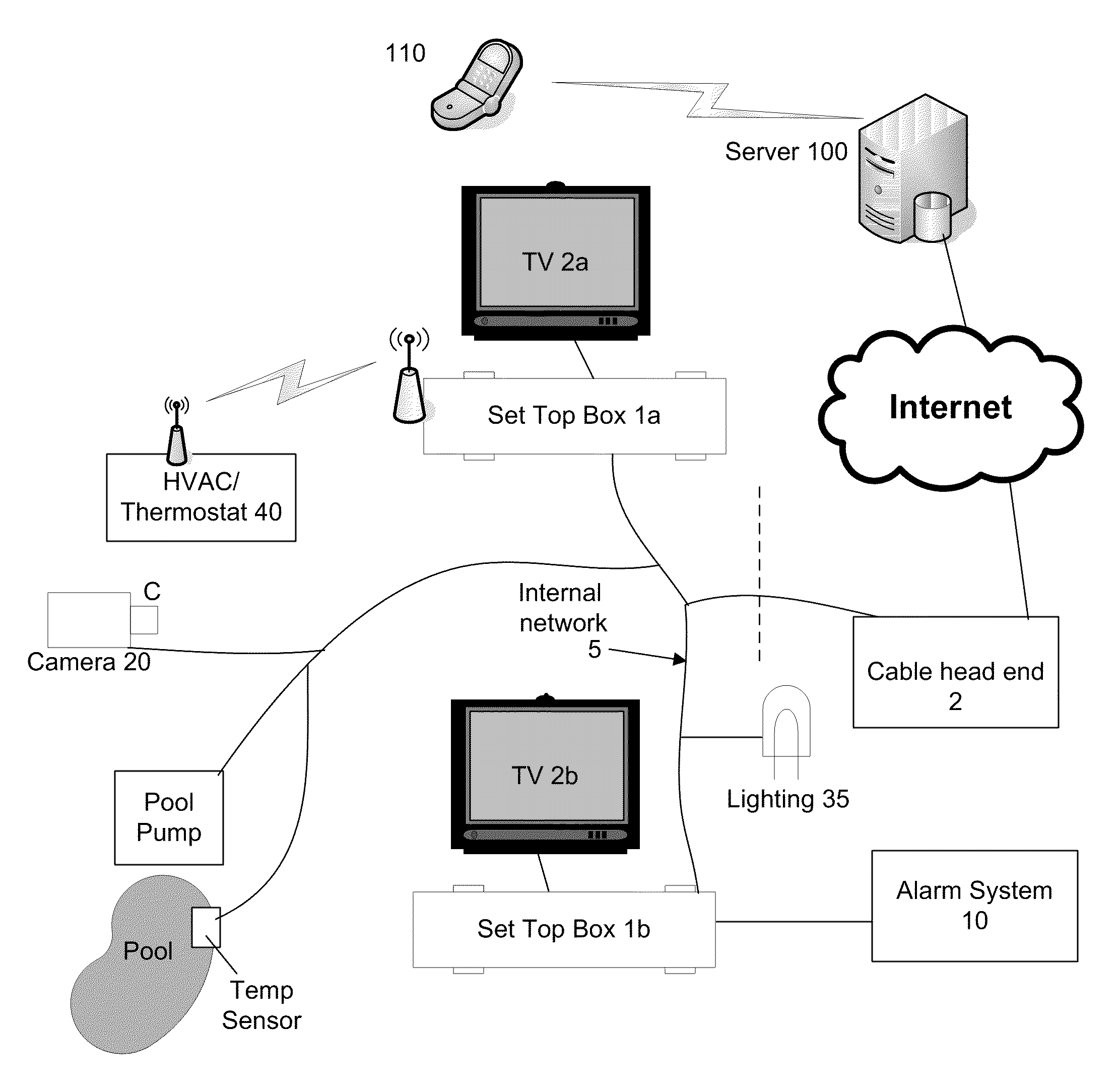
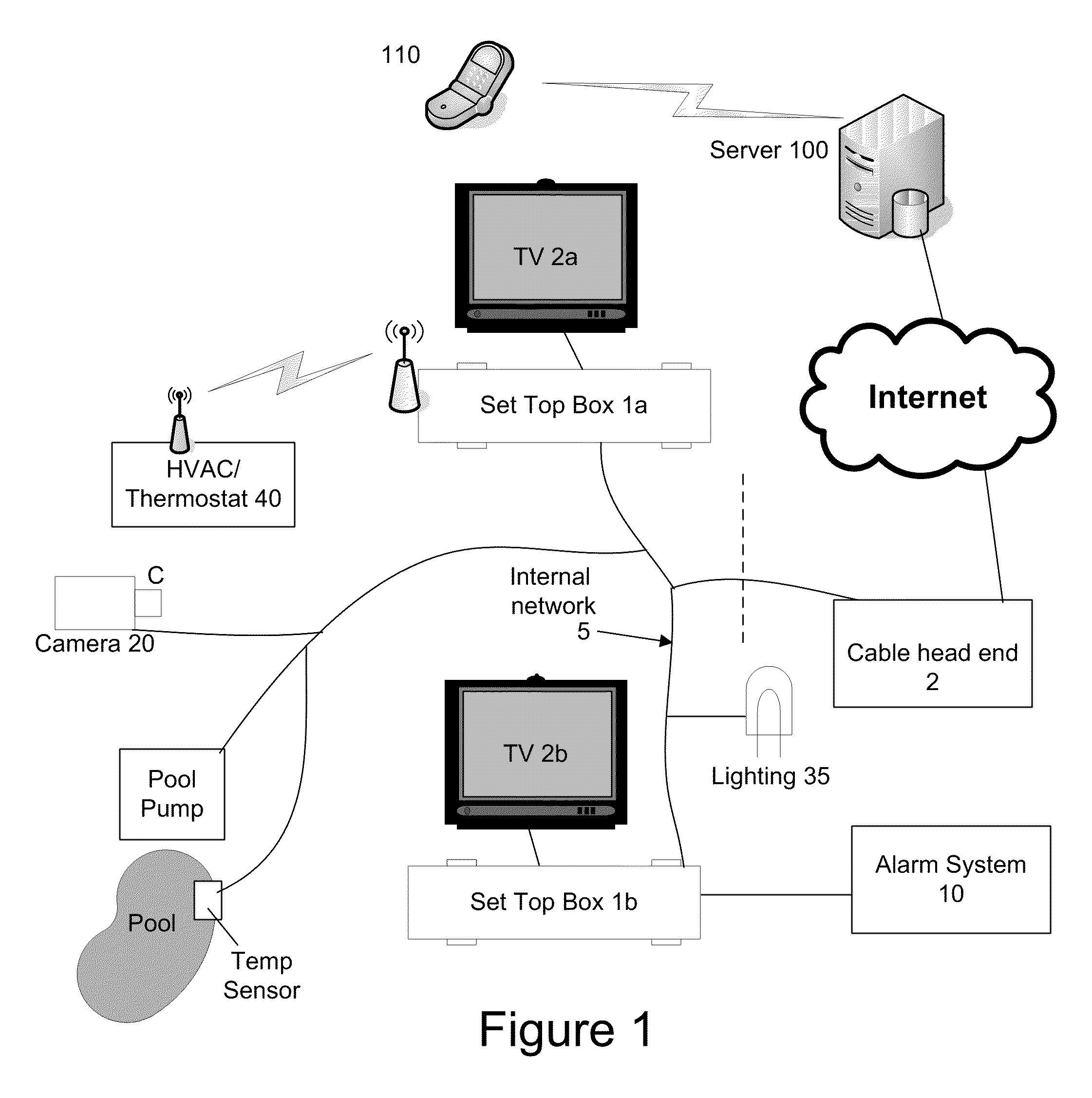
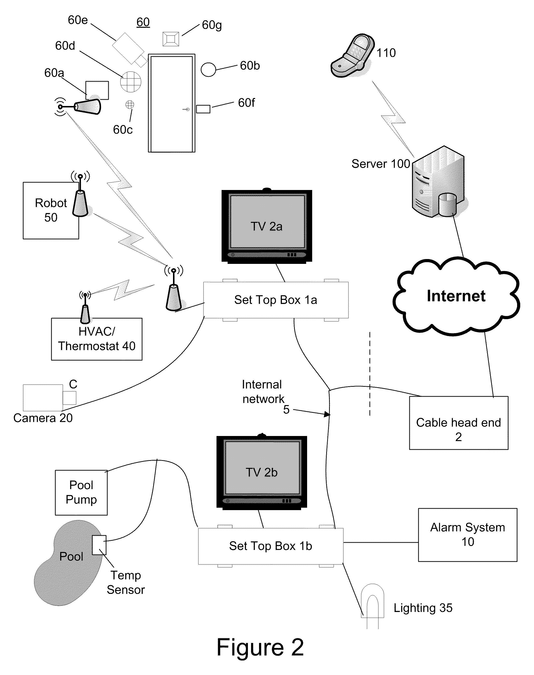
[0006]The present invention provides a system, method and device for providing communications with an in-home system at a residence of a user. In one embodiment, the method comprises receiving digital television programming content from a television service provider, receiving a first user input of a selected digital television programming content, in response to receiving the first user input, causing the selected digital television programming content to be displayed on a television, receiving a message from an in-home system, in response to receiving the message, causing a notification to be displayed on the television as an overlay over the displayed television programming content, receiving a first user command, determining a first control message to transmit to the in-home system in response to receiving the first user command, transmitting the first control message to the in-home system, wherein the in-home system may comprise a video camera, an entry way security system, an HVAC system, a lighting system, an alarm system, or other in-home system. User inputs may be received via a remote control to a set top box or from a computing device at a remote computer system through the internet and / or a mobile telephone network.

Problems solved by technology

Additionally, personal computers are often relegated to a home office and / or are often not turned on while consumers watch television.

Method used


Image

  • In-home System Monitoring Method and System
  • In-home System Monitoring Method and System
  • In-home System Monitoring Method and System

Examples


Embodiment Construction

[0012]In the following description, for purposes of explanation and not limitation, specific details are set forth, such as particular networks, communication systems, computers, terminals, devices, components, techniques, data and network protocols, software products and systems, operating systems, development interfaces, hardware, etc. in order to provide a thorough understanding of the present invention.

[0013]However, it will be apparent to one skilled in the art that the present invention may be practiced in other embodiments that depart from these specific details. Detailed descriptions of well-known networks, communication systems, computers, terminals, devices, components, techniques, data and network protocols, software products and systems, operating systems, development interfaces, and hardware are omitted so as not to obscure the description.

[0014]FIG. 1 illustrates an example embodiment of an in-home system (connected to a cable head end) according to an example embodime...


PUM


Abstract

A system, method and device for providing communications with an in-home system at a residence of a user are provided. In one embodiment, the method comprises receiving digital television programming content from a television service provider, receiving a first user input of a selected digital television programming content, in response to receiving the first user input, causing the selected digital television programming content to be displayed on a television, receiving a message from an in-home system, in response to receiving the message, causing a notification to be displayed on the television as an overlay over the displayed television programming content, receiving a first user command, determining a first control message to transmit to the in-home system in response to receiving the first user command, transmitting the first control message to the in-home system, wherein the in-home system may comprise a video camera, an entry way security system, an HVAC system, a lighting system, an alarm system, or other in-home system. User inputs may be received via a remote control to a set top box or from a computing device at a remote computer system through the internet and / or a mobile telephone network.

Description

CROSS REFERENCE TO RELATED APPLICATIONS[0001]This application claims priority to U.S. Provisional Patent Application Ser. No. 60 / 084,476, filed Jul. 29, 2009, which is incorporated herein by reference in its entirety for all purposes.FIELD OF THE INVENTION[0002]The present invention generally relates to data communications and more particularly, to a system and method for monitoring and controlling various in-home systems such as HVAC, alarm systems, video cameras, and others.BACKGROUND OF THE INVENTION[0003]With the advent of Digital Television (DTV) comes the ability to create interactive TV (ITV) programming. The “old” analogue set-top box cable units are being phased out and replaced by more robust digital units. Digital cable head-ends and their supporting infrastructure have made it possible to create and deploy TV applications. These applications allow the viewer to call up movies on demand, play games, record TV programs, etc.[0004]Many consumers would desire to monitor and ...

Claims


Application Information

Patent Timeline
Patent Type & Authority Applications(United States)
IPC IPC(8): H04N7/18H04N5/00
CPCH04L12/2818H04L12/282H04L2012/285H04N7/186H04N21/25875H04N21/4131H04N21/4104H04N21/42202H04N21/4223H04N21/43615H04N21/4882H04N21/6118H04N21/6131H04N21/4147H04N21/4112
Inventor PINO, JR., ANGELO J.SATTAR, MOHAMMED
Owner PINO JR ANGELO J
Learn More